

The best caster configuration for heavy equipment is determined by how the equipment must move—not simply by how many casters can fit beneath the frame. Two machines with the same weight and the same caster model can behave very differently if one uses two swivel and two rigid casters while the other uses four swivel casters. One may track predictably through a long aisle; the other may move sideways in a tight work cell but require more control to travel straight.
That difference becomes more important as load increases. Under an extremely heavy machine, every change of direction requires the swivel casters to align while carrying substantial vertical load. A long wheelbase can increase the space needed to turn. An uneven floor can shift most of the load onto fewer casters than expected. A high or offset center of gravity can make abrupt steering, braking or slope travel unsafe even when every caster has enough nominal capacity.
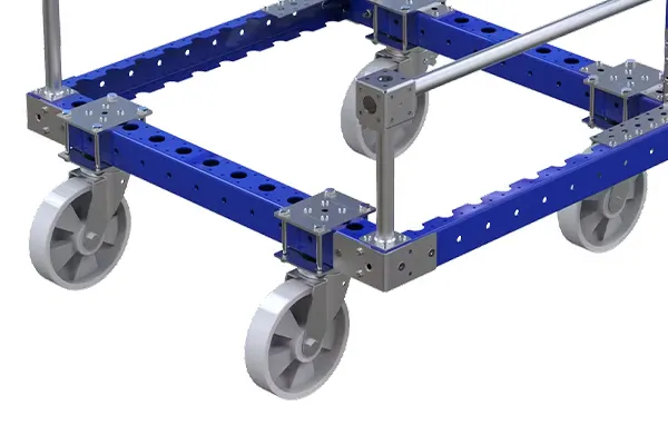
This guide compares swivel and rigid casters, four-caster arrangements, six-caster layouts, diamond and rocker configurations, and platforms using eight or more casters. It also explains how movement method, caster spacing, load distribution, wheel diameter, directional locks and equipment geometry affect the final choice.
If you already know the required capacity and operating conditions, explore BigCaster’s extra heavy duty casters. If the load class is still uncertain, first compare heavy duty vs extra heavy duty casters.
Important: A layout that works on a low-speed shop cart may not be suitable for powered towing, slopes, high-center-of-gravity equipment or movement around personnel. The final equipment design should be reviewed and tested under the maximum intended load and the worst route conditions.
Quick Answer: Which Caster Layout Should You Use?
For many rectangular carts that are moved manually along predictable routes, two swivel casters and two rigid casters provide a practical balance of steering and straight-line tracking. The rigid pair helps the cart hold a direction, while the swivel pair allows it to turn.
Choose a different starting layout when the movement requirement is different:
| Equipment movement | Useful starting configuration | Why it may fit | Main limitation to evaluate |
|---|---|---|---|
| Frequent straight travel with normal turns | 2 swivel + 2 rigid | Predictable tracking with controlled steering | Cannot move directly sideways |
| Short-distance multidirectional positioning | 4 swivel | Can approach, rotate and move laterally | Harder to track straight under a very heavy load |
| Multidirectional positioning plus straight routes | 4 swivel with directional locks on selected positions | Changes between free swiveling and directionally controlled travel | Lock orientation and operating procedure must be defined |
| Long industrial platform | 4 swivel end casters + 2 center rigid casters in an engineered rocker layout | Creates a central turning influence and supports a long frame | Contact loads change as the platform rocks or the floor varies |
| Long equipment with predictable one-direction movement | Application-specific rigid/swivel or multiple rigid arrangement | Can prioritize tracking and structural support | Turning and lateral positioning may be restricted |
| Powered towing | Engineered rigid/swivel or directionally controlled layout | Can be designed for stable tracking at the specified speed | Static catalog capacity does not validate towing suitability |
| Equipment with eight or more caster positions | Load-equalized or structurally analyzed multi-caster system | Can support a large footprint and distributed frame loads | Installed capacity cannot be assumed to equal every rating added together |
These are selection directions, not universal prescriptions. Equipment dimensions, center of gravity, travel direction, floor, speed, duty cycle and control method can change the correct answer.
Why Caster Layout Matters More as Equipment Gets Heavier
A caster system has to do more than support vertical weight. While the equipment moves, the layout also determines how it starts, tracks, turns, stops and reacts to an obstacle.
Swivel alignment requires force
A swivel caster trails behind its vertical swivel axis. When the equipment begins moving in a new direction, the wheel and fork must rotate into alignment. The required force depends on the carried load, swivel geometry, wheel material, floor friction, bearing condition and direction of the existing wheel orientation.
With a light cart, an operator may barely notice this alignment. With an extremely heavy machine, four swivel casters pointing in different directions can create a substantial initial steering event. A cart may technically be capable of moving in any direction while still being difficult to start in the direction the operator wants.
Rigid casters create directional control
A rigid caster does not rotate around a vertical swivel axis. Its fixed wheel plane resists sideways movement and gives the equipment a preferred travel direction. That behavior helps a heavy cart track through aisles, but it also means the equipment needs enough room to follow an arc around a turn.
Equipment geometry changes turning behavior
Wheelbase, track width and caster position establish the geometry of the mobile base. A long rectangular platform using two rigid and two swivel casters generally needs more turning space than a short platform with the same caster models. Moving the caster positions inward can reduce some dimensions but also reduces the support footprint and may increase structural loads in the frame.
Not every installed caster carries the same load
A rigid frame on an uneven floor may temporarily rest on only three of four casters. A six-caster platform may place most of the load on the two center casters if they are intentionally mounted lower. Manufacturing tolerances, frame deflection and floor irregularities can also leave one or more wheels lightly loaded or off the floor.
This is why the number of mounting positions and the effective number of load-bearing casters are not always the same. Use the Extra Heavy Duty Caster Load Capacity Guide before selecting a layout by nominal total capacity.
Stability depends on more than caster rating
The projection of the loaded center of gravity should remain within the equipment’s effective support area. Steering, braking, acceleration, a sloped floor or a shifting load can reduce the available stability margin. A high equipment load does not automatically create stability; the location of that weight matters.
For this reason, caster placement for heavy equipment must be considered together with the frame, payload, operating procedure and route.
Swivel Casters vs Rigid Casters
The decision is not usually whether swivel casters or rigid casters are universally better. It is which combination creates the movement the equipment actually needs.
How a swivel caster works
A swivel caster has a raceway or swivel section between the mounting plate and fork. This allows the fork and wheel to rotate around a vertical axis. The wheel axle is normally offset from that axis so the caster can trail and align with travel.
Swivel casters provide:
- Direction changes without lifting the equipment
- Rotation and repositioning in restricted areas
- The possibility of lateral movement when all caster positions can swivel
- Flexible approach angles for docking or machine placement
The trade-offs include:
- More force and movement during swivel alignment
- More components to inspect in the swivel section
- Less inherent straight-line tracking than a rigid caster
- A swept swivel envelope that requires clearance beneath the equipment
- Possible shimmy or unstable behavior if speed, geometry, loading or caster selection is unsuitable
For very high loads, the swivel raceway, fork, axle, bearings, plate and fasteners all have to be evaluated—not only the wheel.
How a rigid caster works
A rigid caster, also called a fixed caster, holds its wheel in one plane. It can roll forward and backward but does not steer independently.
Rigid casters provide:
- Predictable straight-line tracking
- A simple directional role in a mixed layout
- Fewer steering components than a swivel assembly
- Resistance to unwanted lateral movement
Their limitations are equally important:
- A group of rigid casters cannot move directly sideways
- Turning requires the complete equipment to follow an arc, pivot around selected wheels or use a special layout
- Incorrectly aligned rigid casters can create scrub and high rolling force
- Long wheelbases can require considerable turning space
Swivel vs rigid caster comparison
| Selection factor | Swivel caster | Rigid caster |
|---|---|---|
| Allowed wheel direction | Changes around the vertical swivel axis | Fixed in one wheel plane |
| Turning and positioning | High flexibility | Depends on its relationship with swivel casters or pivot geometry |
| Straight tracking | May require directional control | Naturally establishes a travel direction |
| Lateral movement | Possible in an all-swivel layout | Not possible through the rigid position |
| Initial direction change | Requires the caster to swivel into alignment | Wheel orientation is already fixed |
| Swept clearance | Requires space for the fork, wheel and accessories to rotate | Usually has a smaller fixed envelope |
| Components to inspect | Wheel, axle, fork, swivel raceway, locks and mounting | Wheel, axle, fork and mounting |
| Common role in a mixed layout | Steering and maneuvering | Tracking and directional stability |
Many heavy duty casters are available in swivel, rigid and braking versions. The correct versions should be selected as one coordinated system rather than as unrelated components.
Start With the Equipment’s Movement Pattern
Before choosing the number and location of casters, document every way the equipment will move. A layout optimized for one movement pattern may be poor at another.
Occasional maintenance movement
Some machines stay in one position for months and move only during installation, cleaning or maintenance. Their caster systems may travel very little, but they can remain heavily loaded for long periods.
Important questions include:
- Will casters continuously support the operating load, or will leveling feet or machine mounts take over after positioning?
- Can the machine be unloaded before movement?
- Is multidirectional positioning required near the final location?
- Could the wheel tread develop compression set or flat spotting during long stationary periods?
- How will the load be safely transferred between casters and fixed supports?
Four swivel casters can be useful for final positioning, but total locks, directional locks or separate leveling devices may be required. A wheel brake alone should not be assumed to make an operating machine stable.
Frequent manual movement
For a heavy cart moved by operators throughout a shift, the caster layout directly affects push, pull and steering effort. Two swivel and two rigid casters are often a useful starting point because the rigid pair keeps the equipment from wandering during straight travel.
However, the project must also consider:
- Maximum acceptable starting and sustained push force
- Handle location and height
- Whether operators push, pull or use both directions
- Route length and number of turns
- Wheel diameter, material and bearings
- Load height and visibility
- Floor joints, debris and slopes
If the fully loaded equipment exceeds reasonable manual control, changing the caster layout alone may not solve the problem. A powered mover, different route or revised handling process may be necessary.
Tight-area positioning
Machinery placed between production lines may need to move laterally, rotate within its own footprint or approach a mounting point from several directions. A four-swivel layout supports this movement better than a conventional two-rigid/two-swivel arrangement.
The design should then manage the weaknesses of an all-swivel platform. Directional locks can make selected swivel casters behave like rigid casters for straight travel. Adequate swivel clearance prevents wheels, brakes or forks from contacting the equipment frame. A defined operator procedure can prevent one lock from being engaged in an unintended orientation.
Long, predictable routes
When equipment travels mainly along long warehouse or factory aisles, straight tracking may be more valuable than the ability to move in every direction. A mixed layout with rigid casters can reduce steering corrections. Wheelbase, turning areas and docking requirements still have to be mapped before final placement.
Powered towing
Powered towing introduces speed, heat, repeated shock, continuous travel and lateral forces that a manually pushed cart may never experience. Provide the caster manufacturer with:
- Maximum and normal towing speed
- Loaded weight and center of gravity
- Distance per trip and trips per shift
- Turning radius and number of turns
- Tow direction and whether reverse travel occurs
- Floor joints, thresholds, ramps and outdoor sections
- Braking method and stopping distance
- Required caster and wheel maintenance interval
Do not approve a towing layout from static capacity alone. The manufacturer should confirm the proposed caster construction, bearing system, wheel material, swivel geometry and dynamic operating conditions.
Layout 1: Two Swivel and Two Rigid Casters
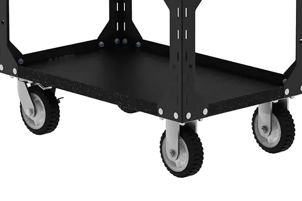
The two swivel and two rigid caster configuration is one of the most common arrangements for rectangular carts. The rigid casters are mounted parallel to establish a straight travel direction. The swivel casters steer the opposite end around turns.
Why this layout works
During straight travel, the rigid wheels resist sideways drift while the swivel wheels trail in alignment. During a turn, the swivel end follows the steering input and the cart travels around an arc influenced by the rigid pair.
This arrangement can work well for:
- Heavy material carts
- Tooling and die-handling carts
- Maintenance platforms
- Long carts moving through aisles
- Equipment that follows repeatable routes
- Loads that need directional control more than lateral positioning
Main advantages
- Good straight-line tracking
- Familiar handling behavior for many operators
- Fewer swivel sections than an all-swivel platform
- Less tendency to move sideways unintentionally
- Practical for repeated travel along predictable routes
Main limitations
- The cart cannot translate directly sideways
- It needs room to follow a turning arc
- A long wheelbase increases maneuvering space
- Tight docking from the side may be difficult
- The rigid casters must be mounted parallel to avoid scrub
Should the swivel casters be at the push end?
On many manually pushed carts, the swivel casters are placed near the operator’s handle so the operator can steer that end while the rigid pair tracks. This is a common starting direction, not an absolute rule.
The correct placement depends on whether the equipment is normally pushed or pulled, whether it must reverse frequently, where the tow bar or handle is located, and how it enters turns. A platform that is routinely towed from one end may need a different arrangement from a short manual cart. Test the intended travel directions rather than assuming that one placement works for every machine.
Design checks for a 2 + 2 layout
Confirm that:
- Both rigid casters are parallel to the intended straight travel line.
- The swivel casters have enough space to rotate through 360 degrees under load.
- Brakes, directional locks and frame members do not interfere with the swept envelope.
- The wheelbase allows the required turn within the real aisle.
- The handle or tow point gives the operator adequate control.
- The loaded center of gravity stays within the effective support area.
- The load calculation accounts for uneven floors and possible three-point support.
Layout 2: Four Swivel Casters
A four-swivel layout allows the platform to change direction at every corner. It can move forward, backward, diagonally or sideways and can often rotate within a smaller area than a comparable two-rigid/two-swivel platform.
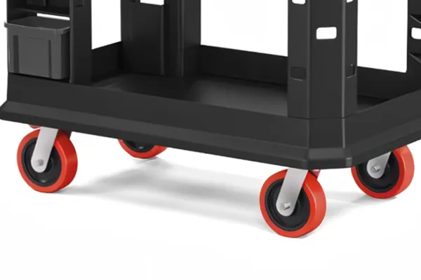
This makes four swivel casters useful for:
- Machinery that needs precise final positioning
- Short movements within a production cell
- Platforms that must approach equipment from different directions
- Loads that need lateral translation
- Equipment used where conventional turning arcs are unavailable
Why four swivel casters can be difficult under heavy loads
Direction freedom is not the same as easy control. If the four swivel casters are pointing in different directions at rest, they must rotate before the platform can begin moving along the new line. On an extremely heavy platform, that alignment can create high initial force and unexpected motion.
Once moving, an all-swivel platform also lacks the fixed directional reference provided by rigid casters. It may require continuous operator correction on a long route. A side force, uneven floor or misaligned caster can cause the equipment to drift.
Four swivel casters should therefore be selected for a real multidirectional requirement—not simply because “more swivel means more maneuverable.”
Directional locks can create two movement modes
A directional lock restrains a swivel caster in a selected orientation while still allowing the wheel to roll. When properly configured, selected swivel casters can provide straight-line control when locked and multidirectional positioning when released.
For example, a four-swivel platform may use directional locks on two positions:
- Unlocked mode: all four casters swivel for lateral movement and close positioning.
- Directionally locked mode: two casters act as rigid positions for predictable travel.
The locking direction, position and operating procedure must match the equipment. Engaging locks that point in different directions can prevent movement or impose high forces on the caster and frame.
Wheel brake, total lock and directional lock are different
| Control device | Wheel rolling | Swivel rotation | Primary purpose |
|---|---|---|---|
| Wheel brake | Restrained | Normally remains free | Helps prevent rolling at that wheel |
| Total lock | Restrained | Restrained | Holds both wheel and swivel section at that caster |
| Directional lock | Free to roll | Held in a selected direction | Changes a swivel caster into a temporary rigid-tracking position |
These functions are not interchangeable. A brake should be selected by the required parking, operating and steering behavior—not by the generic phrase “locking caster.”
Design checks for a four-swivel layout
- Measure starting and steering forces at maximum load.
- Confirm straight tracking over the longest route.
- Decide whether directional locks are required and where they will be placed.
- Check the accessibility of every pedal or actuator.
- Verify that a released brake or lock cannot strike the frame during swiveling.
- Test approach, stopping and parking on every permitted floor condition.
- Prevent use on slopes unless the full system and operating procedure are approved for it.
Layout 3: Six-Caster Configurations for Long Heavy Platforms
Adding two casters to a long platform can provide structural support and change its turning behavior, but there is no single six-caster arrangement. The position, caster type and mounted height of every unit define how the platform behaves.
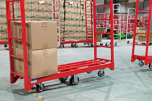
One common concept uses:
- Two rigid casters near the center, mounted parallel to the long axis
- Four swivel casters near the corners or ends
- A controlled height relationship that allows the platform to pivot mainly around the center pair
This is often described as a six-caster rocker layout.
How the center rigid pair changes steering
If the two center rigid casters carry the dominant load, they create a central directional axis. The end swivel casters stabilize the platform and support it as the load shifts. Compared with placing the turning influence at one end of a very long wheelbase, the center pair can help the platform pivot in a smaller area.
The word “rocker” is important. If the center pair is intentionally mounted slightly lower, the platform can transfer support from one end to the other. The four corner casters do not necessarily carry equal load at the same time.
Why six does not mean divide by six
Never select a six-caster system by automatically dividing total weight by six. Depending on geometry and floor condition:
- The two center casters may carry a large portion of the load.
- Only one end pair may be fully loaded at a given moment.
- Frame deflection may overload selected mounting positions.
- A floor joint may transfer load abruptly from one wheel to another.
- Height tolerances can change which casters contact the floor.
An initial capacity calculation must use the effective load-bearing positions for the proposed design. The equipment engineer should also evaluate local frame reactions at each mounting plate.
You can use BigCaster’s caster wheel load capacity calculator for preliminary screening, but a rocker or other load-shifting layout requires an equipment-specific analysis.
When a six-caster layout may be useful
- Long die or mold transport carts
- Extended machinery bases
- Large tooling platforms
- Heavy loads distributed along a long frame
- Equipment that needs a smaller effective pivot length than a corner-mounted 2 + 2 layout
Six-caster layout risks
- Rocking can be unacceptable for tall or unstable loads.
- End caster loads can change sharply during transitions.
- A flexible frame can create unpredictable contact conditions.
- Slope travel can reduce stability.
- A height difference that helps turning may complicate loading and parking.
- Operator handling may differ between forward, reverse and rotating movement.
Final approval should include a loaded route test, not only a static floor test.
Layout 4: Diamond and Rocker Caster Arrangements
“Diamond layout” can refer to arrangements in which the caster positions form a diamond rather than a rectangle. A typical concept places the primary rigid wheels at the left and right sides near the middle of the equipment, with swivel or stabilizing casters toward the front and rear. The center wheels may be mounted to carry the dominant load so the platform can pivot around them.
Potential advantages
- A long platform can rotate around a central wheel pair.
- The effective turning length may be shorter than with rigid casters at one end.
- Fewer casters may dominate rolling resistance during a pivot.
- The layout can provide economical directional control in suitable applications.
Important stability trade-offs
A diamond or rocker arrangement can create a smaller effective support area at certain moments. If the front and rear casters are lightly loaded, the machine may rock around the central axis. A tall, offset or shifting payload can magnify this behavior.
Use particular caution when the application includes:
- High center of gravity
- Liquid, suspended or shifting loads
- Sloped floors
- Rapid acceleration or braking
- People riding or working from the equipment
- Loading or unloading near an end
- Outdoor surfaces or significant floor irregularities
A diamond layout should be treated as an equipment design, not a universal caster shortcut. The height relationship, frame stiffness, center of gravity, support geometry and operating limits must be defined together.
What About Eight or More Casters?
Large machinery bases and transport platforms may use eight, twelve or more casters. Installing more wheels can create additional mounting points and potentially distribute forces into a large frame, but it does not guarantee equal load sharing.
Why load sharing becomes difficult
Imagine eight nominally identical casters bolted to a rigid frame. Small differences in caster overall height, plate flatness, weld distortion, bolt preload, tire deformation or floor elevation can determine which wheels touch first. The loaded frame then bends until more positions engage. The resulting loads depend on the stiffness of both the frame and the caster assemblies.
Simply adding eight individual caster ratings can therefore produce a misleading system capacity.
Load-equalizing approaches
Depending on the application, designers may use:
- Equalizing beams or walking-beam arrangements
- Bogie-mounted wheel pairs
- Spring-loaded caster assemblies
- Individually adjustable mounting positions
- Flexible or articulated subframes
- Hydraulic or mechanical suspension systems
- A deliberately conservative effective-caster calculation
Each approach changes stability, travel height, maintenance and dynamic response. It must be assessed as part of the complete machine.
Questions for a multi-caster platform
- How many casters are expected to carry the load in the worst condition?
- Is the frame stiff enough to distribute load, or flexible enough to equalize it?
- What overall-height tolerance is permitted at each mounting position?
- How does the system respond when one wheel crosses an obstacle?
- Can a failed or unloaded caster be detected during inspection?
- Does the layout scrub during turning?
- How are brakes or directional controls coordinated?
- Can every caster be accessed for maintenance and replacement?
For unusually high loads or non-standard layouts, BigCaster can review a custom heavy duty caster solution using equipment drawings and operating details.
How Wheelbase and Track Width Affect Performance
Caster type alone does not establish handling. The distances between caster positions are just as important.
Wheelbase
Wheelbase is the longitudinal distance between the primary front and rear support or steering positions. In a conventional 2 + 2 layout, increasing the wheelbase generally increases the space required to turn around the rigid pair. It can also improve directional stability along a straight route.
A shorter wheelbase can make a cart feel more responsive, but bringing the casters inward changes frame loading and reduces the length of the support footprint. The final dimension must balance maneuverability, equipment structure and stability.
Track width
Track width is the lateral distance between the left and right wheel lines. A wider track generally creates a wider support footprint, which can improve lateral stability. It may also increase the overall equipment width and restrict passage through doors or aisles.
Support polygon and center of gravity
Connect the caster contact positions that are effectively carrying the load; the area inside those points forms the support polygon. For static stability on a level floor, the vertical projection of the loaded center of gravity should remain within this area with an appropriate design margin.
The real margin can decrease when:
- The floor slopes
- The equipment accelerates, turns or brakes
- The load shifts
- One caster loses contact
- The machine is loaded near an edge
- A towing force is applied above floor level
This is why placing casters close to the center just to reduce turning space can create a poor result for tall equipment.
Swivel radius and interference
Every swivel caster needs a clear circular envelope for the wheel, fork and brake. Large wheels, long swivel lead, wide dual wheels and brake mechanisms can all increase this space.
Check the complete drawing at every caster position. A caster that collides with a frame beam cannot align properly, and a brake that becomes inaccessible after rotation is not a usable control.
For a deeper size comparison, see How Wheel Diameter Affects Extra Heavy Duty Caster Performance.
How Load Distribution Changes With Caster Layout
Start with the maximum operating weight:
Maximum operating weight = equipment dead weight + maximum payload + tooling, batteries and accessories
For preliminary selection:
Required rated capacity per caster = maximum operating weight × application allowance ÷ effective load-bearing casters
The application allowance and effective caster count should be chosen from the real design, not from a universal percentage or the total number of purchased casters.
Four-caster equipment
On a rigid four-caster frame, an uneven floor can place the effective load on three casters. An offset center of gravity may load one end or side more heavily. Evaluate both effects.
Six-caster equipment
In a center-rigid rocker configuration, the two middle casters may be intentionally dominant. One end pair may stabilize the equipment while the other is lightly loaded. Use reactions from the actual geometry rather than one-sixth of total weight.
Equipment with eight or more casters
Load distribution depends strongly on frame stiffness, equalizing mechanisms, caster compliance and floor profile. A structural model or measured load test may be appropriate.
Dynamic load transfer
Static distribution changes when a wheel encounters a threshold, the equipment turns, a tow vehicle accelerates or a brake is applied. Wheel material and diameter affect the severity of these events, but no tread can eliminate dynamic loading.
Capacity must refer to the complete caster assembly and its interface with the equipment. The wheel, bearings, axle, fork, swivel section, top plate, bolts, welds and frame all carry force. For the full calculation process, review the extra heavy duty caster load capacity guide.
Single-Wheel vs Dual-Wheel Casters in a Layout
Once the positions are defined, decide whether each position should use a single-wheel or dual-wheel assembly.
Why dual wheels are considered
A dual-wheel caster can place two wheels within one assembly. Depending on its design, this may provide high capacity, spread floor contact across two treads and achieve a useful capacity within a particular overall-height envelope.
If the two wheels can rotate independently, differential wheel movement may also influence scrub during swiveling. But dual wheels are not automatically easier to turn. Tread material, wheel width, swivel lead, bearings, load and floor friction still matter.
Layout implications of dual wheels
- The assembly is usually wider, so swivel clearance must be checked.
- Floor contact does not guarantee that both wheels share load perfectly.
- Debris can collect between the wheels in some environments.
- Brake and lock design may differ from a single-wheel caster.
- Replacement access and axle service should be considered.
- A dual-wheel assembly still counts as one caster position when evaluating frame reactions, even though it contains two wheels.
The choice is explained in detail in Single-Wheel vs Dual-Wheel Extra Heavy Duty Casters. You can also compare available dual-wheel casters.
Match the Layout to Wheel Diameter and Material
Caster configuration, wheel size and tread material interact. Selecting them in separate purchasing steps can create a system that has enough capacity but performs poorly.
Wheel diameter
Larger wheels generally cross floor joints and small obstacles more easily than smaller wheels under otherwise comparable conditions. They can reduce the geometric severity of an obstacle and may improve manual movement.
However, larger wheels also increase overall caster height and often increase the swivel envelope. On an all-swivel platform, an increase in wheel diameter can create interference that did not exist in the original layout. Raising the machine can also reduce stability if the loaded center of gravity rises with it.
Wheel material
- Polyurethane: A common balance of load performance, wear resistance and floor protection for smooth industrial floors.
- PA or MC nylon: Hard, efficient rolling on suitable floors, with less cushioning and more transmitted vibration.
- Rubber: Better cushioning and noise control where an adequate high-load construction is available, usually with greater rolling resistance.
- Cast iron or steel: High load and low deformation for specialized applications, but harsh on floors and poor at absorbing shock.
Read Best Wheel Materials for Extra Heavy Duty Casters before finalizing the tread and core.
Swivel lead and tread friction
Swivel lead—the horizontal distance between the vertical swivel axis and wheel axle—affects how a caster trails and responds to steering forces. Tread friction and deformation affect how much force is required to rotate the loaded caster. Two caster models with the same wheel diameter and capacity can therefore feel very different in the same layout.
Ask for drawings and application data rather than selecting by diameter and rating alone.
Recommended Caster Layouts by Application
| Application | Starting layout to evaluate | Main objective | Critical checks |
|---|---|---|---|
| Manually pushed heavy cart | 2 swivel + 2 rigid | Straight tracking with controlled steering | Push force, handle position, wheelbase, floor joints |
| Machinery requiring lateral positioning | 4 swivel | Multidirectional placement | Directional locks, total locks, swivel clearance |
| Long die or mold cart | 4 swivel ends + 2 center rigid in an engineered rocker layout | Central pivoting with support along a long frame | Contact loads, rocking, frame stiffness, load height |
| Powered tow cart | Manufacturer-approved rigid/swivel or directional layout | Stable tracking under dynamic service | Speed, distance, heat, shock, turns and braking |
| Low-profile machinery base | Application-specific 4-caster or multi-caster layout | High capacity within limited mounting height | Stability, wheel diameter, floor loading, locking method |
| Rarely moved production machine | 4 swivel or mixed layout with separate leveling/support system | Precise maintenance positioning and stable operation | Load-transfer procedure, total locks, leveling feet |
| High-center-of-gravity equipment | Wide support footprint with controlled steering | Preserve stability margin | Center of gravity, slopes, acceleration, turn speed |
| Very large platform | Structurally analyzed, load-equalized multi-caster system | Support a large frame while maintaining contact | Equalization, mounting tolerances, obstacle load transfer |
Use this table to define candidates, not to skip validation. The same application name can involve very different loads, routes and operating risks.
Step-by-Step Caster Layout Selection Process
Step 1: Calculate the maximum operating load
Include equipment, payload, batteries, tooling, accessories and temporary loads. Do not use empty machine weight.
Step 2: Locate the loaded center of gravity
Record its horizontal position and height for normal, maximum and offset load conditions. Identify whether the payload can shift.
Step 3: Define every movement mode
State whether the equipment is manually pushed, pulled, powered, towed, rotated in place, moved laterally or repositioned only during maintenance.
Step 4: Map the route
Measure straight distances, aisle widths, turn areas, doorways, slopes, expansion joints, thresholds, gaps and floor changes. The worst section often determines the selection.
Step 5: Choose the required movement behavior
Decide whether the priority is:
- Straight tracking
- Multidirectional positioning
- A combination of both using directional locks
- Central pivoting for a long platform
- Towing stability
Step 6: Select candidate layouts
Compare at least the relevant 2 + 2, four-swivel and multi-caster arrangements. Review wheelbase, track width, swivel envelope and support geometry for each one.
Step 7: Determine effective load-bearing positions
Account for uneven floors, rocker geometry, frame deflection and mounting tolerances. Do not divide by every installed caster unless the design genuinely equalizes the load.
Step 8: Select wheel, bearing and caster construction
Match wheel material, diameter, wheel width, bearings, swivel structure, axle, mounting plate and finish to the load, floor, route, speed and environment. The broader process is covered in How to Choose Extra Heavy Duty Casters for Industrial Equipment.
Step 9: Specify control devices
Define wheel brakes, total locks, directional locks, floor locks, leveling feet or external brakes according to how the equipment must park and operate.
Step 10: Validate the complete system
Review drawings, confirm mounting strength, inspect clearances and conduct loaded testing over the real or simulated route. Include starting, straight travel, turns, lateral movement, obstacle crossing, stopping, parking and emergency procedures.
Common Caster Layout Mistakes
Assuming four swivel casters are always easier to move
Four swivel casters allow movement in more directions, but each caster must align with a new direction. Under an extremely heavy load, alignment and straight-line control can require more effort than a 2 + 2 layout.
Dividing the load equally by every installed caster
Floor variation, frame deflection and intentional rocker geometry can concentrate load on fewer positions. Installed caster count is not automatically effective caster count.
Ignoring the loaded center of gravity
A platform can have adequate vertical caster capacity and still have insufficient stability. Check the center of gravity with the real payload, not just the empty frame.
Treating all locks as the same
A wheel brake restrains rolling, a total lock restrains rolling and swivel motion, and a directional lock controls swivel orientation while allowing travel. Specify the function required.
Placing casters inward only to reduce turning space
Inboard caster positions may reduce the wheelbase or overall footprint, but they also change frame reactions and reduce the support polygon. Tall equipment needs particular care.
Ignoring the swivel envelope
The wheel, fork and brake need space to rotate. Interference can prevent steering, damage components or make controls inaccessible.
Selecting a manual-cart layout for powered towing
Towing changes speed, impact, heat and lateral forces. A caster that works during an occasional manual move is not automatically suitable for repeated powered service.
Using a catalog layout without testing the route
An arrangement can perform well on a smooth test floor and poorly at the first expansion joint, slope or narrow turn. Validate the complete route at maximum intended load.
Information to Send a Caster Manufacturer
For a useful caster layout recommendation, provide:
- Maximum loaded equipment weight
- Empty equipment weight
- Load dimensions and center-of-gravity location
- Equipment length, width and frame construction
- Number and location of available mounting points
- Mounting plate and bolt-hole dimensions
- Maximum allowable overall caster height
- Manual push, manual pull, powered drive or towing method
- Normal and maximum speed
- Distance per trip and trips per shift
- Required movement directions
- Minimum turning area and aisle width
- Floor material and condition
- Largest joints, thresholds and obstacles
- Slopes and ramps
- Water, oil, chemicals, debris and temperature
- Required brakes, total locks and directional locks
- Desired wheel material and diameter, if already constrained
- Drawings, photographs and videos of the equipment and route
BigCaster manufactures heavy duty and extra heavy duty caster solutions in Yangjiang, Guangdong, China. Standard products include polyurethane, rubber, PA nylon, MC nylon, cast iron and all-steel wheel options, including single- and dual-wheel constructions. Custom mounting, load and functional requirements can be reviewed for OEM and project applications.
Frequently Asked Questions About Heavy Equipment Caster Layouts
What is the best caster configuration for heavy equipment?
There is no single best configuration for every machine. Two swivel and two rigid casters are a strong starting point for straight travel and normal turns. Four swivel casters suit multidirectional positioning, while long platforms or powered towing may require an engineered six-caster or directionally controlled layout. Load, route, center of gravity and movement method should decide the final arrangement.
Are swivel casters or rigid casters better for very heavy loads?
Neither type is automatically better based on load alone. Rigid casters provide straight tracking, while swivel casters provide steering and positioning. Capacity depends on the complete wheel, fork, axle, bearings, swivel section and mounting. Extremely heavy equipment commonly uses a coordinated combination of both types.
Should swivel casters be installed at the front or rear?
On many manually pushed carts, swivel casters are placed near the operator’s handle and rigid casters at the opposite end. However, towing direction, reversing frequency, equipment length and docking requirements can justify another arrangement. Evaluate the normal direction of control and test the loaded equipment in every permitted direction.
Are four swivel casters better than two swivel and two rigid casters?
Four swivel casters are better when the equipment must move laterally or reposition in a tight area. Two swivel and two rigid casters usually provide better straight-line tracking. If both behaviors are required, four swivel casters with directional locks on selected positions may be worth evaluating.
How many casters are needed for extremely heavy equipment?
The answer depends on more than total capacity. Equipment size, frame strength, center of gravity, floor, turning behavior and load equalization all matter. Adding more casters can create more mounting points, but it does not guarantee equal load sharing. Calculate with an effective caster count supported by the actual design.
Can total load be divided equally by six casters?
Not automatically. In a six-caster rocker layout, the center pair may carry most of the load while one end pair is only stabilizing the platform. Even in a nominally level arrangement, frame and floor tolerances can create unequal contact. Determine wheel reactions from the layout and validate them under load.
What is a directional lock caster?
A directional lock holds a swivel caster in a selected travel direction while allowing its wheel to roll. It lets a swivel position temporarily provide rigid-like tracking. It is different from a wheel brake, which restricts wheel rotation, and a total lock, which restrains both wheel and swivel motion.
What caster layout is best for powered towing?
Powered towing requires an application-specific layout approved for the loaded weight, speed, distance, turns, floor, braking and duty cycle. Stable tracking may involve rigid casters, directional locks or specialized swivel construction. Do not select the system from static load rating or a manual-cart diagram alone.
How does wheelbase affect caster turning radius?
In a conventional mixed layout, a longer distance between steering and rigid positions generally requires more room to turn. Shortening the wheelbase can improve maneuverability but changes frame loading and support geometry. Use the actual equipment envelope and route to compare candidate layouts.
Are diamond caster layouts stable?
They can be suitable for particular low-speed equipment, but stability depends on the effective support points, wheel-height relationship, center of gravity, loading method and floor. A layout that rocks around a center wheel pair needs special caution with tall, shifting or offset loads and on slopes.
Can dual-wheel casters reduce the number of caster positions?
Sometimes a dual-wheel assembly can provide the required capacity at fewer mounting positions, but capacity is not the only criterion. Frame reactions, floor loading, swivel effort, overall width, stability and redundancy must still be evaluated. Do not remove positions solely by comparing catalog ratings.
Final Selection Principle
The best heavy equipment caster layout is the one that creates controlled movement under the real operating load.
- Use two swivel and two rigid casters when straight tracking and conventional turning are the main requirements.
- Use four swivel casters when lateral and multidirectional positioning are essential, then evaluate directional locks for straight travel.
- Consider an engineered six-caster rocker layout for a long platform only after calculating how load transfers among the center and end positions.
- Treat diamond layouts as complete stability and handling designs, not as universal shortcuts.
- Use structural analysis or load-equalizing mechanisms when a platform has eight or more caster positions.
- Obtain manufacturer confirmation for powered towing, slopes, speed or severe dynamic service.
The layout should then be matched with the correct capacity, wheel diameter, tread material, bearings, mounting interface and controls. Browse BigCaster’s extra heavy duty caster range, or send us the equipment weight, dimensions, route, movement method and drawings for a project-specific caster configuration.