

Extra heavy duty caster load capacity should be calculated per caster assembly—not by choosing the largest number in a catalog or simply dividing equipment weight by the number of wheels installed. Real equipment rarely distributes its load perfectly. Uneven floors, an offset center of gravity, frame deflection, acceleration, turning and impact can make one caster carry substantially more than the average.
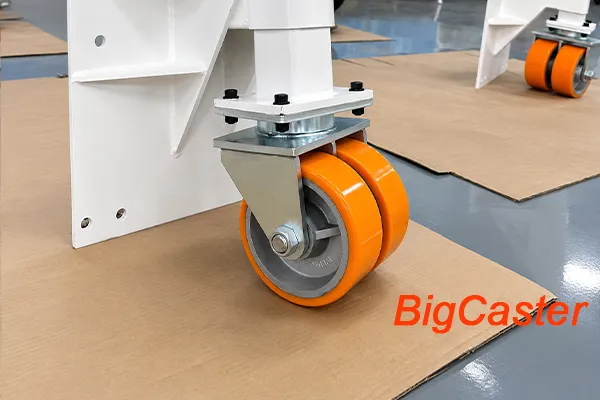
A practical calculation therefore needs three things: the maximum total loaded weight, the effective number of casters supporting that weight and an application factor that reflects actual operating conditions. Static, dynamic and impact loads must also be distinguished before a product rating is accepted.
This guide explains the calculation process for four-caster equipment, multi-caster platforms, uneven loads and powered applications. It also clarifies how to use BigCaster’s per-caster load pages without confusing an individual caster rating with the capacity of a complete cart.
Quick Formula for Extra Heavy Duty Caster Load Capacity
The following formula is a useful starting point:
Required capacity per caster = (equipment weight + maximum payload + accessories) ÷ effective supporting casters × application factor
In symbols:
Cmin = (We + Wp + Wa) ÷ Ne × K
Where:
- Cmin = minimum required rated capacity per caster assembly
- We = equipment dead weight
- Wp = maximum payload
- Wa = additional weight such as batteries, tooling, liquids and accessories
- Ne = effective number of supporting casters
- K = application factor for departures from the caster’s standard rating conditions
The answer is a minimum target. The selected swivel or rigid caster should have a verified dynamic rating equal to or higher than the result under the intended speed, floor, temperature and duty cycle.
Quick Calculation Example
Consider a machine platform with:
- Equipment weight: 1,000 kg
- Maximum payload: 3,000 kg
- Total loaded weight: 4,000 kg
- Four casters installed
- Three effective supporting casters
- Illustrative application factor: 1.3
The calculation is:
4,000 ÷ 3 × 1.3 = 1,733 kg per caster
The project should therefore start with caster assemblies dynamically rated above approximately 1,733 kg each under the required operating conditions.
The factor 1.3 is used here only to demonstrate the calculation. It is not a universal safety factor. A powered outdoor platform crossing large obstacles may require a substantially different factor or product-specific derating. Use BigCaster’s caster wheel load capacity calculator for an initial result, then verify the application details before selecting a model.
What Does Caster Load Capacity Mean?
Caster load capacity is the maximum load a specific wheel or caster assembly can support under defined conditions. The phrase sounds simple, but buyers must identify exactly what has been rated.
A supplier may publish a rating for:
- A wheel without a caster rig
- A complete rigid caster
- A complete swivel caster
- A dual-wheel caster assembly
- A static condition
- A dynamic test at a defined speed
These values are not automatically interchangeable.
Wheel Capacity Is Not Always Complete Caster Capacity
A high-capacity wheel installed in an undersized swivel rig does not create a high-capacity caster. The limiting component may be the tread, wheel core, bearing, axle, fork, swivel section, mounting plate or fastener system.
For example, a solid steel wheel may tolerate a very high compressive load, but the caster assembly can still be limited by swivel-bearing stress or fork deformation. Conversely, a heavily reinforced rig cannot compensate for a wheel tread that overheats, flat-spots or separates under the actual load and duty cycle.
Always compare the rating of the complete configuration to be purchased: wheel, bearings, axle and caster rig together.
Per-Caster Capacity Is Not the Capacity of the Complete Cart
BigCaster’s load-category pages refer to the rated load of one caster assembly where applicable. A page labeled 5,000 lbs casters therefore helps buyers find individual caster configurations around that load rating. It does not mean a four-caster platform has an automatically approved capacity of 20,000 lbs.
The total safe equipment load depends on:
- How many casters effectively carry the load
- Whether the center of gravity is centered
- Equipment-frame stiffness
- Floor flatness
- Static or dynamic use
- Speed and travel distance
- Obstacles and impact
- The manufacturer’s rating conditions
Buyers who already know their required per-caster rating can browse the BigCaster extra heavy duty caster range. Those who do not should complete the calculation and application review first.
Step 1: Calculate the Maximum Total Loaded Weight
Start with the heaviest condition the equipment will realistically experience—not its empty weight or average daily load.
Use:
Total loaded weight = equipment dead weight + maximum payload + additional weight
Equipment Dead Weight
Equipment dead weight includes the structure to which the casters are mounted:
- Cart, platform or machine frame
- Enclosures and panels
- Motors, gearboxes and drives
- Permanently mounted tooling
- Guarding and control systems
Maximum Payload
Payload means the heaviest material, product, die, mold, fixture or component that will be carried during normal and foreseeable operation. Do not use the average payload if the equipment is sometimes loaded more heavily.
Additional Weight Commonly Missed
Calculation errors often come from components added after the main equipment weight was estimated. Check for:
- Batteries and chargers
- Hydraulic power units
- Fuel, water, oil or other liquids
- Hoses and cable reels
- Removable jigs and fixtures
- Spare tooling
- Operator platforms
- Future accessories already planned for the design
Suppose an industrial platform weighs 1,200 kg, carries a 5,500 kg machine and includes a 300 kg battery and hydraulic unit. Its total is not 5,500 kg. It is:
1,200 + 5,500 + 300 = 7,000 kg
All later caster calculations must begin with the 7,000 kg total.
Step 2: Determine the Effective Number of Supporting Casters
The installed caster count and the effective supporting caster count can be different. This is one of the most important concepts in heavy equipment mobility.
If four caster positions shared weight perfectly, the baseline load would be total weight divided by four. In practice, rigid equipment frames and imperfect floors often create three-point support. One caster can become lightly loaded while the other three carry most of the equipment weight.
Why Four Casters Are Often Calculated as Three
Three contact points define a stable plane. A fourth point requires the floor, mounting points and caster heights to align closely enough for equal contact. Small differences can come from:
- Uneven concrete
- Welding distortion in the equipment frame
- Tolerance differences in caster overall height
- Top-plate or frame deflection
- Debris under one wheel
- A load that twists the chassis
For a rigid four-caster platform without a verified load-equalizing system, using three effective supporting casters is a common conservative starting point:
Baseline capacity per caster = total loaded weight ÷ 3
This does not mean the fourth caster is unnecessary. All four help stabilize and move the equipment. The calculation simply recognizes that the load may not be shared equally at every moment.
Three-point support is a practical selection principle, not a universal legal requirement or substitute for structural analysis. A platform with a properly engineered equalizing suspension may use all four mounting positions more predictably. A highly flexible frame may behave differently from a rigid welded structure. The actual design must be reviewed.
How Much Weight Can Four Casters Hold?
The answer is not always four times the catalog rating.
If each caster is rated at 5,000 lbs, the mathematical sum is 20,000 lbs. However, a rigid platform calculated with three effective supporting casters has a baseline of:
3 × 5,000 = 15,000 lbs before additional application requirements
That does not establish a final approved equipment capacity. Speed, impact, load distribution and the rating basis still need to be considered. It does show why “four 5,000 lb casters equal a 20,000 lb cart” can be an unsafe assumption.
How to Calculate Capacity for Six or Eight Casters
Do not automatically divide the load by six or eight. Do not automatically apply N − 1 either.
Long multi-caster platforms create additional questions:
- Does the frame bend between mounting points?
- Are the middle casters fully loaded or slightly clear of the floor?
- Is the payload concentrated over one end or in the center?
- Are all caster heights controlled closely?
- Does the system use rocker beams, walking beams or equalizing suspension?
- Are spring-loaded casters intended to equalize load or only absorb vibration?
A long six-caster chassis may place most of its weight on four casters while two contribute only under certain deflection conditions. In another design, the center pair may become overloaded when the frame bends. The effective supporting count must be determined from the platform structure, load position and equalizing method.
For multi-caster equipment, use structural calculations, load measurements or a verified equalizing design rather than relying only on caster quantity.
Step 3: Account for Uneven Load Distribution
Even when every caster touches the floor, each one may carry a different load. The equipment’s center of gravity controls how the weight is distributed among the mounting positions.
Uneven distribution commonly occurs when:
- A motor or gearbox is mounted at one end
- A machine column is located near one corner
- A die or mold is loaded from one side
- A liquid moves inside a tank
- A lift, arm or workpiece changes position during operation
- The payload is temporarily placed on an edge during loading
Off-Center Load Example
Consider equipment with a total loaded weight of 6,000 kg. Measurements or design calculations show that 60% of the load is carried by the front side and 40% by the rear.
Front-side load:
6,000 × 60% = 3,600 kg
If two front casters share this load equally:
3,600 ÷ 2 = 1,800 kg per front caster before the application factor
Rear-side load:
6,000 × 40% = 2,400 kg
Rear baseline:
2,400 ÷ 2 = 1,200 kg per rear caster before the application factor
Dividing the total by four would produce 1,500 kg and underestimate the load on each front caster by 300 kg before any allowance for movement or impact.
The designer can use different front and rear caster ratings, but many OEMs standardize on the higher rating to simplify maintenance and replacement. The correct decision also depends on wheel diameter, swivel/rigid layout and available mounting space.
When the center of gravity changes during use, calculate the worst foreseeable position rather than the parked or unloaded condition.
Step 4: Understand Static, Dynamic, Impact and Side Loads
An extra heavy duty caster can experience several kinds of load. Each stresses the assembly differently.
| Load type | Meaning | Typical condition | Why it matters |
|---|---|---|---|
| Static load | Weight supported while the equipment is stationary | Parked machinery, storage platforms | Usually easier for the caster than loaded movement, but long-term tread deformation can matter |
| Dynamic load | Weight supported while rolling under defined conditions | Moving carts, mobile machinery and platforms | Primary rating for most mobile equipment |
| Impact load | A short-duration force caused by a sudden event | Floor joints, dropped loads, dock plates and collisions | Can bend forks, damage bearings or crack wheels even when static weight seems acceptable |
| Side load | Lateral force applied to the caster assembly | Tight turns, towing misalignment, side impact and braking | Can stress the fork, kingpin, swivel section and mounting bolts |
Static Load Capacity
Static capacity describes performance while the caster remains stationary. It is relevant to equipment that spends most of its life parked, but it is not sufficient for a cart or machine that moves while loaded.
Long-term static loading can still affect resilient wheel materials. Polyurethane and rubber treads may develop temporary or permanent flat spots depending on load, hardness, temperature and storage time. The complete caster and equipment frame must also resist permanent deformation.
Dynamic Load Capacity
Dynamic capacity is established while the wheel or caster moves under controlled test conditions. Those conditions can include speed, obstacle size, test duration, ambient temperature and floor surface.
For mobile equipment, dynamic capacity is normally the relevant catalog value. However, a dynamic rating does not mean the caster can carry the same load at any speed, over any floor and for any number of hours.
Published ratings should be compared together with the manufacturer’s test basis. Standards such as the DIN EN 12527–12533 and corresponding ISO wheel-and-caster test series define procedures for particular applications, but the buyer still has to match the tested condition to real use.
Impact Load
Impact occurs when motion changes suddenly. Common sources include:
- Crossing expansion joints
- Dropping from a floor plate
- Hitting a small obstacle
- Loading a die abruptly
- Sudden towing acceleration or braking
- A cart striking a curb or machine base
Impact force depends on speed, wheel diameter, obstacle geometry, wheel resilience, equipment mass and chassis stiffness. Because these variables interact, impact cannot be represented accurately by one generic percentage for every project.
If repeated shocks are unavoidable, the solution may involve a larger wheel, resilient tread, spring-loaded caster, reduced speed, improved travel path or stronger caster assembly. Simply selecting a higher static rating may not solve the actual failure mode.
Side Load
Caster catalogs focus mainly on vertical capacity, but lateral forces become increasingly important with multi-ton equipment. Side loading can occur when a tow vehicle pulls at an angle, a rigid caster is forced sideways or a swivel caster changes direction abruptly.
The swivel lead, fork geometry, bearing system, directional locks, mounting plate and fasteners all influence resistance to side loads. Applications involving frequent tight turns or powered towing should be reviewed beyond the vertical load formula.
Step 5: Choose an Appropriate Application Factor
The application factor K accounts for departures from the conditions used to establish the caster’s standard rating. It may reflect floor quality, obstacles, speed, movement method, environment and operating frequency.
There is no universal factor that is correct for every extra heavy duty caster.
Relative severity generally increases as follows:
| Operating condition | Relative margin typically required |
| Indoor manual movement on smooth, level floors | Lower |
| Indoor manual movement across small joints | Moderate |
| Indoor powered towing | Higher |
| Outdoor manual movement on uneven surfaces | Higher |
| Outdoor powered movement across significant obstacles | Highest; engineering review required |
Factors that can increase the required margin include:
- Poor load distribution
- Higher speed
- Continuous operation
- Outdoor travel
- Rough floors
- Large obstacles relative to wheel diameter
- Repeated changes of direction
- Impact or dropped loads
- Extreme temperatures
- Corrosive or contaminated environments
- A high consequence of failure
Some manufacturer guides publish numerical ranges for defined combinations of manual or powered movement, indoor or outdoor use and obstacle height. Those ranges are useful only when their assumptions match the selected caster series and actual application.
Avoid Double-Counting Without Understanding the Formula
The effective supporting count and the application factor solve different problems:
- Ne accounts for how many casters actually share the load.
- K accounts for operating severity beyond the standard rating condition.
Using three effective supports for a four-caster platform and then applying a factor may be appropriate. However, blindly combining N − 1 with a generic 30%, another “safety factor” and an undocumented speed reduction can produce an arbitrary result rather than a verified design.
Define what each adjustment covers. Then use the product manufacturer’s rating and derating guidance for the conditions not already included.
Step 6: Adjust for Floor Conditions and Obstacles
Floor condition changes both load distribution and impact.
Important surfaces and route features include:
- Smooth or rough concrete
- Epoxy coatings
- Asphalt
- Steel plate
- Expansion joints
- Dock plates
- Elevator gaps
- Rails and channels
- Outdoor potholes
- Metal chips and debris
Obstacle Height Relative to Wheel Diameter
The same obstacle can be minor for one wheel and severe for another. A 10 mm joint is a larger percentage of a 4-inch wheel diameter than of a 12-inch wheel diameter. The smaller wheel must climb a steeper relative obstacle and can generate a stronger shock at the same speed.
This is why wheel diameter and load capacity cannot be separated completely. A small wheel with a very high static rating may still perform poorly on a route containing gaps and floor joints.
When obstacles control the application, consider:
- Increasing wheel diameter
- Reducing speed
- Choosing a resilient tread
- Repairing or bridging floor gaps
- Using shock-absorbing or spring-loaded casters
- Increasing structural and load margin after engineering review
This guide focuses on the load effect. The detailed choice between wheel diameters should be handled as a separate part of the overall heavy duty caster selection process.
Step 7: Adjust for Speed, Travel Distance and Duty Cycle
A caster that moves five metres once a week experiences a very different duty cycle from one traveling several kilometres per shift.
Speed and repeated operation can cause:
- Increased heat in the tread
- Bearing temperature rise
- More frequent obstacle impacts
- Faster tread wear
- Bearing fatigue
- Swivel instability or flutter
- Higher force during braking and direction changes
Manual Movement
Walking-speed manual use on a smooth indoor floor is a common baseline condition in caster testing and selection guides. Even then, operators may struggle to start or swivel a multi-ton load before the caster reaches its structural capacity. Capacity and ergonomic push force must be checked separately.
Powered Towing, AGVs and AMRs
Do not apply a manual-push rating automatically to powered use. Confirm:
- Maximum operating and emergency speed
- Acceleration and braking
- Towing direction and tow-bar geometry
- Distance per cycle
- Cycles per hour or shift
- Continuous run time
- Floor joints and turning radii
- Wheel-tread temperature
- Bearing and swivel design
The manufacturer may require derating at higher speeds or may recommend a caster designed specifically for continuous-duty towing. If appropriate speed-capacity data are unavailable, the general formula alone cannot validate the application.
Complete Caster Load Capacity Calculation Workflow
Use the following process for an initial engineering review:
- Calculate equipment dead weight. Include the complete frame, machinery and permanent systems.
- Add the maximum payload and accessories. Use the heaviest foreseeable operating condition.
- Locate the worst-case center of gravity. Do not assume an equal corner load.
- Determine the effective supporting caster count. Consider floor flatness, frame stiffness and equalizing mechanisms.
- Choose the relevant rating type. Use a verified dynamic rating for equipment that moves while loaded.
- Identify operating severity. Review speed, route, obstacles, duty cycle, temperature and movement method.
- Apply a defined application factor or product-specific derating. Document what the adjustment covers.
- Select a rating above the calculated minimum. Do not round down to the nearest product.
- Verify the complete caster assembly. Check the wheel, bearing, axle, rig, mounting plate and brakes.
- Confirm the equipment structure. The chassis and fasteners must transfer the rated load safely.
This workflow produces a selection target, not a certification of the complete machine. High-consequence equipment should be validated through engineering analysis, appropriate testing and the applicable safety requirements.
Worked Example 1: Four-Caster Indoor Machinery Platform
An indoor machinery platform has:
- Equipment structure: 1,000 kg
- Maximum machinery and payload: 3,000 kg
- Total loaded weight: 4,000 kg
- Four rigidly mounted casters
- Smooth indoor concrete with occasional small joints
- Manual, intermittent movement
Assume three effective supporting casters and an illustrative factor of 1.3:
4,000 ÷ 3 × 1.3 = 1,733 kg per caster
The buyer should select a complete caster assembly with a verified dynamic capacity above 1,733 kg under the defined conditions. A product group around 4,000 lbs per caster may be a starting point because 4,000 lbs is approximately 1,814 kg, but the exact product’s published lb and kg values, wheel material, speed and use conditions must be confirmed.
If the platform later changes to powered towing, the result should be reviewed again rather than assuming the manual-use selection remains valid.
Worked Example 2: Off-Center Extra Heavy Duty Equipment
An industrial machine and platform weigh 6,000 kg in the maximum operating condition. The front of the machine carries 60% of the load.
Front pair:
6,000 × 0.60 ÷ 2 = 1,800 kg per caster before the application factor
Rear pair:
6,000 × 0.40 ÷ 2 = 1,200 kg per caster before the application factor
If the verified application factor were 1.4 for this specific scenario, the preliminary targets would be:
- Front: 1,800 × 1.4 = 2,520 kg per caster
- Rear: 1,200 × 1.4 = 1,680 kg per caster
The front selection could begin around the 6,000 lbs caster category, while the rear could begin around a lower rating. However, standardizing all four positions on the higher capacity may simplify spare parts and prevent installation errors. The final decision must also consider swivel/rigid layout, wheel diameter and mounting dimensions.
Worked Example 3: Six-Caster Long Platform
A 12,000 kg platform uses six casters along a long welded frame. Dividing by six gives 2,000 kg per caster, but this result assumes equal load sharing.
Before using it, the engineer must determine:
- Whether the frame remains straight under full load
- Whether all six mounting points are coplanar
- Where the payload is concentrated
- Whether the center casters become overloaded during frame deflection
- Whether rocker beams or another equalizing mechanism are installed
If analysis shows that only four casters reliably support the worst-case position, the baseline becomes:
12,000 ÷ 4 = 3,000 kg per caster before the application factor
That is 50% higher than the simple six-way division. Depending on the verified operating factor, the project may move toward 10,000 lbs caster options or another engineered configuration.
The example demonstrates why a six-caster capacity formula cannot be based only on the number six.
Worked Example 4: Powered Towing
A heavy platform weighs 8,000 kg fully loaded and uses four casters. A preliminary three-support calculation gives:
8,000 ÷ 3 = 2,667 kg per caster before operating adjustments
The platform is towed indoors at a specified maximum speed and crosses expansion joints during every route. At this point, a generic multiplier is not enough. The buyer must obtain or confirm:
- Caster capacity at the towing speed
- Permitted obstacle height
- Maximum continuous run time
- Wheel-tread heat performance
- Bearing suitability
- Swivel stability
- Acceleration and braking conditions
Only after these data are reviewed should the final per-caster rating be selected. If the manufacturer does not provide appropriate speed and duty information, choosing an apparently large catalog capacity does not validate the towing application.
Browse BigCaster Casters by Per-Caster Load Rating
The following pages help buyers find products by individual caster rating. They are commercial filters, not substitutes for the calculation above. Always verify the exact lb and kg rating on the individual product page because conversions may be rounded and products within a category can have different ranges.
| Load category | BigCaster page | Typical use in the selection process |
| 1,000 lbs per caster | 1000 lbs Casters | Lower end of BigCaster’s industrial load navigation |
| 2,000 lbs per caster | 2000 lbs Casters | Heavy industrial configurations |
| 3,000 lbs per caster | 3000 lbs Casters | Higher-capacity carts and equipment |
| 4,000 lbs per caster | 4000 lbs Casters | Extra heavy machinery and platform directions |
| 5,000 lbs per caster | 5000 lbs Casters | Multi-ton industrial applications |
| 6,000 lbs per caster | 6000 lbs Casters | Higher concentrated-load requirements |
| 10,000 lbs per caster | 10000 lbs Casters | Very high-capacity equipment configurations |
| 20,000 lbs per caster | 20000 lbs Casters | Exceptional loads requiring engineering review |
Do not select a category by rounding a calculated requirement downward. If the minimum result is 4,200 lbs per caster, a 4,000 lbs caster does not meet it. Start at a rating above the requirement and confirm the product’s conditions.
Common Caster Load Capacity Calculation Mistakes
1. Ignoring Equipment Dead Weight
The payload is only part of the load. Machine frames, batteries, hydraulics and fixtures can add substantial weight.
2. Dividing by Every Installed Caster
Installed casters do not always share load equally. Determine the effective supporting count.
3. Assuming N − 1 Solves Every Multi-Caster Design
The N − 1 shortcut is commonly used for four-caster equipment but does not automatically model long six- or eight-caster frames.
4. Using Static Capacity for Moving Equipment
Mobile equipment normally requires a verified dynamic rating under suitable conditions.
5. Applying One Universal Safety Factor
The correct margin depends on speed, floor, obstacles, movement method and the manufacturer’s rating basis.
6. Ignoring the Center of Gravity
An offset or moving load can make one side carry far more than the average.
7. Ignoring Impact
Floor joints, gaps and dropped loads can create peak forces not represented by static weight.
8. Treating a Wheel Rating as a Caster-Assembly Rating
The fork, swivel, axle or mounting plate may be the limiting component.
9. Assuming More Casters Always Increase Capacity Proportionally
Additional casters help only when the frame and equalizing design distribute load to them.
10. Ignoring the Equipment Mounting Structure
A high-rated caster attached to a weak chassis does not create a high-rated system.
Information to Send for a Load-Capacity Review
For a useful recommendation, provide:
- Equipment dead weight
- Maximum payload
- Additional batteries, liquids, tooling and accessories
- Overall dimensions and center-of-gravity location
- Number and positions of casters
- Swivel and rigid caster arrangement
- Equipment-frame material and mounting details
- Manual, tugger, AGV or other movement method
- Maximum speed and acceleration
- Travel distance and cycles per shift
- Floor material and condition
- Joint, gap and obstacle dimensions
- Indoor or outdoor use
- Temperature range
- Water, oil, chemicals, dust or metal debris
- Required wheel diameter and maximum overall height
- Brake and directional-lock requirements
BigCaster can review these details and recommend an appropriate starting configuration. For buyers still deciding which product class is suitable, the guide to heavy duty vs extra heavy duty casters explains the difference between the two categories.
How BigCaster Supports High-Capacity Caster Projects
BigCaster manufactures heavy duty and extra heavy duty caster wheels for industrial carts, machinery, logistics systems, container handling, construction and other high-load equipment. Available product directions include polyurethane, rubber, PA and MC nylon, cast iron and steel wheels in swivel, rigid, braking and project-specific configurations.
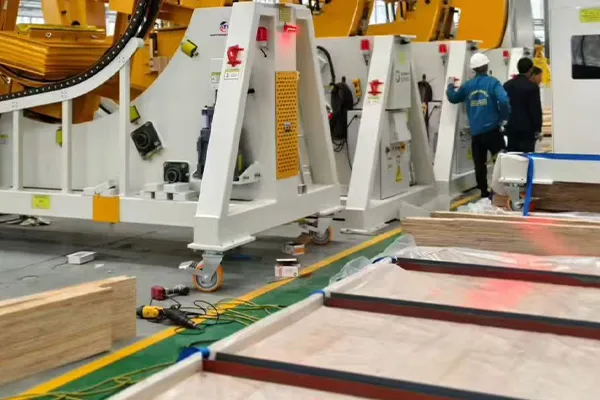
Our load pages are organized around per-caster ratings, while final project selection considers the full operating condition. BigCaster can also review customized load, mounting and configuration requirements for OEM and project buyers.
Send the total loaded weight, caster layout, speed, travel route, floor, environmental conditions and mounting dimensions. We can then help identify suitable extra heavy duty caster options and confirm which product data still need to be validated before production.
Frequently Asked Questions
Caster capacity is normally stated for one wheel or one complete caster assembly, depending on the product description. BigCaster load-category pages refer to one caster assembly where applicable. The capacity of a complete set must be calculated from the effective supporting caster count and actual operating conditions.
Add the equipment dead weight, maximum payload and accessories. Divide the total by the effective number of supporting casters, then apply a factor or derating appropriate to the floor, speed, movement method, impact and duty cycle. Select a caster whose verified rating meets or exceeds the result.
On an uneven floor or a slightly distorted rigid frame, one of four casters can become lightly loaded while the other three carry most of the weight. Three effective supports are therefore a common conservative starting point for a four-caster platform without a verified equalizing system.
Not automatically. Four ratings add mathematically to 20,000 lbs, but the platform may not distribute weight equally. A three-support baseline would be 15,000 lbs before additional operating factors. Center of gravity, movement, speed, obstacles, frame strength and the caster’s rating conditions must also be reviewed.
There is no single factor for every application. Indoor manual movement on smooth floors may require a lower margin than powered outdoor movement over obstacles. Use the factor or derating guidance for the selected caster series and define which risks it covers.
Static capacity applies while the caster is stationary. Dynamic capacity applies while it is rolling under defined test conditions. Mobile equipment should normally be selected using a suitable dynamic rating, not a higher static value.
First determine how the platform frame and load distribute weight. Do not assume every wheel carries an equal share and do not apply N − 1 mechanically. Long frames may deflect, while rocker beams, suspension or equalizing systems can change the effective supporting count.
It can. Higher speed, longer travel, repeated impact, acceleration and heat can require load derating or a continuous-duty caster design. Confirm the rated speed, duty cycle and allowable obstacle conditions with the manufacturer.
Not necessarily. The complete dual-wheel assembly must be rated as a unit. Axle strength, bearings, wheel spacing, rig construction and load sharing determine the final capacity.
Conclusion
Extra heavy duty caster load capacity must be calculated per caster assembly using the maximum total loaded weight, the effective number of supporting casters and verified operating conditions. Dividing weight by every installed caster can underestimate the requirement when the floor is uneven, the center of gravity is offset or a long platform does not distribute load equally.
Use dynamic rather than static ratings for moving equipment, and treat speed, impact, obstacles, towing and duty cycle as real engineering variables. A generic safety multiplier is not a substitute for understanding the manufacturer’s test conditions and derating guidance.
Once the minimum per-caster rating has been calculated, browse BigCaster’s load pages without rounding downward, then confirm the wheel, bearings, rig, mounting structure and environment. For a multi-ton or powered application, contact BigCaster through the extra heavy duty caster range and submit the full operating details for review.