

Larger caster wheels generally cross obstacles more easily and reduce the force required to move heavily loaded equipment, assuming the wheel material, bearings, load and floor remain comparable. Increasing wheel diameter is therefore one of the most effective ways to improve the mobility of an industrial cart or machine.
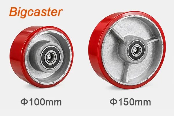
But a larger wheel is not automatically a better caster. More diameter usually means more overall caster height, a larger swivel envelope and a higher equipment mounting surface. It may raise the equipment’s center of gravity, create interference beneath the frame or change the forces acting on the mounting plate. Wheel diameter alone also does not determine load capacity, towing speed or operator safety.
This heavy duty caster wheel diameter guide explains how size affects obstacle crossing, starting and rolling force, shock, rated capacity, overall height, ground clearance, swivel radius, stability and wheel speed. It also compares 6-, 8-, 10- and 12-inch wheels and shows how to select a practical diameter for extra heavy duty equipment.
If you need a complete caster specification rather than a diameter comparison alone, begin with How to Choose Extra Heavy Duty Casters for Industrial Equipment.
Quick Answer: What Does a Larger Caster Wheel Change?
| Performance factor | General effect of increasing wheel diameter | Important limitation |
|---|---|---|
| Obstacle crossing | Usually improves | Obstacle shape, tread, speed and load still matter |
| Starting and rolling force | Usually decreases under comparable conditions | Bearings, tread deformation and floor can override the advantage |
| Impact at floor joints | Usually decreases | A large wheel does not eliminate dynamic shock |
| Load capacity | May increase within a product series | Diameter alone does not establish capacity |
| Overall caster height | Increases | Equipment and working height may become unacceptable |
| Ground clearance | Usually increases | Stability and loading interfaces may change |
| Swivel radius | Usually increases | More space is needed beneath the equipment |
| Center-of-gravity height | Usually rises with the equipment | Tipping margin may decrease |
| Wheel RPM at the same speed | Decreases | Dynamic rating, heat and caster stability still need review |
| Component weight and cost | Often increase | Construction and material determine the actual change |
The best caster wheel size is normally the largest diameter that satisfies the load, route and mobility requirements without violating equipment height, stability, swivel clearance or mounting constraints.
Wheel Diameter Is Not the Same as Caster Height
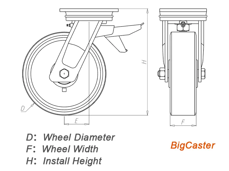
Before comparing caster sizes, separate the dimensions used on a product drawing.
Wheel diameter
Wheel diameter is measured across the outside of the wheel through its center. A nominal 8-inch wheel is approximately 203 mm in diameter, although an actual product drawing may use a metric nominal size such as 200 mm.
The diameter does not include the fork, swivel section or mounting plate.
Wheel width
Wheel width is the nominal width of the tread or wheel body. For a dual-wheel caster, distinguish individual wheel width from the total width of the wheel set.
Width influences load distribution, tread deformation, floor contact and swivel scrub. It should not be treated as part of the wheel diameter.
Overall caster height
Overall height is the vertical distance from the floor to the equipment mounting surface. It includes the wheel radius, fork clearance, swivel structure and top plate.
An 8-inch wheel does not make the complete caster only 8 inches high. The overall caster may be substantially taller than its nominal wheel diameter.
Swivel radius
Swivel radius describes the space required for the wheel and fork to rotate around the caster’s vertical swivel axis. The exact measurement convention should be confirmed on the manufacturer’s drawing.
A larger wheel frequently creates a larger swivel radius, but wheel diameter is not the only variable. Caster offset, fork shape, wheel width and brake construction also affect the swept envelope.
Caster offset or swivel lead
Caster offset is the horizontal distance between the vertical swivel axis and the wheel axle centerline. It affects how the caster trails, swivels and reacts to side forces.
Increasing wheel diameter does not necessarily increase offset by the same amount. Compare actual drawings rather than estimating one dimension from another.
Ground clearance
Ground clearance is the distance between the floor and the lowest relevant part of the equipment or caster structure. It depends on frame geometry and mounted components; it is not automatically equal to the wheel radius.
These distinctions prevent a common sourcing error: replacing a caster based only on wheel diameter and discovering that the equipment height, swivel clearance or mounting geometry no longer works.
1. Wheel Diameter and Obstacle Crossing
Obstacle crossing is where diameter produces its most visible advantage. For a wheel meeting a step, joint edge or piece of debris, the obstacle occupies a smaller proportion of a larger wheel.
Why a larger wheel crosses an obstacle more easily
When a small wheel reaches a sharp step, the contact point can sit relatively high compared with the wheel axle. A substantial horizontal force is then required to rotate the wheel center upward and over the corner.
With a larger wheel:
- The axle is higher relative to the same obstacle
- The obstacle-to-radius ratio is smaller
- The contact geometry is less severe
- The required wheel-center lift is a smaller part of the radius
- The approach is less abrupt
- Impact can be reduced at a controlled speed
This is why large diameter heavy duty casters often perform better on expansion joints, cracked concrete and minor route debris.
An idealized sharp-step model
For a rigid wheel approaching an ideal vertical step very slowly, a simplified moment balance about the step corner gives:
Where:
- (F) is the ideal horizontal force at the axle needed to begin climbing the step
- (W) is the vertical load carried by the wheel
- (R) is the wheel radius
- (h) is the step height
The equation shows the geometric trend: for the same obstacle, increasing radius reduces the required horizontal-force ratio.
Model limitation: This is an idealized quasi-static geometry model. It does not include tread deformation, momentum, friction, bearing resistance, floor compliance, caster swivel behavior, frame deflection, multiple-caster load transfer or impact. It should not be used as a final push-force or safety calculation.
Example: 6-, 8-, 10- and 12-inch wheels at a 10 mm step
| Nominal wheel diameter | Approximate radius | 10 mm obstacle as a percentage of diameter | Idealized (F/W) ratio |
|---|---|---|---|
| 6 in / 152 mm | 76 mm | 6.6% | 0.57 |
| 8 in / 203 mm | 102 mm | 4.9% | 0.48 |
| 10 in / 254 mm | 127 mm | 3.9% | 0.42 |
| 12 in / 305 mm | 152 mm | 3.3% | 0.38 |
In this simplified model, the same 10 mm vertical step becomes progressively less severe as diameter increases. The 12-inch wheel’s ideal force ratio is about one-third lower than the 6-inch wheel’s ratio.
This does not mean the real cart force will equal the table. A polyurethane wheel may deform around an edge, a steel wheel may strike it sharply, and equipment weight may shift among several casters during crossing. The table is valuable because it quantifies the direction of the geometric effect—not because it predicts a finished machine.
Why fixed obstacle-to-diameter rules can mislead
Some guides recommend one fixed ratio between obstacle height and wheel diameter. Such rules may be useful for initial screening, but they should not be treated as universal limits for multi-ton equipment.
Actual performance changes with:
- Soft or hard tread
- Sharp or rounded obstacle edge
- Gap width as well as step height
- Approach speed
- Wheel load
- Single- or dual-wheel structure
- Bearing and fork construction
- Equipment center of gravity
- Whether several wheels cross the joint together
Even standardized wheel tests use defined surfaces, speeds, loads and obstacle proportions. A test condition is not automatically a design limit for every industrial route.
For a critical application, measure the highest step, widest gap and most frequent joint, then test the complete loaded equipment on a representative route.
2. How Wheel Diameter Affects Starting and Rolling Force
Buyers often ask, “Are larger caster wheels easier to push?” The practical answer is generally yes when material, tread width, bearings, alignment, load and floor are comparable. But several different forces are involved.
Starting force
Starting force is the peak force required to begin moving equipment from rest. It may include:
- Wheel tread compression after standing under load
- Bearing seal and lubricant resistance
- Floor indentation
- Adhesion or contamination at the contact patch
- Wheel alignment
- Swivel casters changing from their parked direction
- Brake drag
- Equipment-frame deflection
A larger wheel gives more mechanical leverage against a resistance moment at the hub or contact patch. It can also make minor floor texture less significant relative to the radius.
However, diameter does not remove flat spotting or tread compression. A large, soft wheel that has remained stationary under a multi-ton load can still require substantial breakaway force.
Continuous rolling resistance
Once the equipment moves, the wheel tread repeatedly compresses and recovers as it enters and leaves the contact patch. Energy lost through this deformation contributes to rolling resistance. Bearings, seals, floor roughness, misalignment and debris add further resistance.
A useful simplified relationship is:
Where:
- (F_r) is the horizontal rolling force associated with a resistance moment
- (M_r) is the rolling-resistance moment
- (R) is wheel radius
If the effective resistance moment were unchanged, a larger radius would reduce the required horizontal force. In practice, (M_r) may also change because the larger wheel can use a different tread thickness, width, core or bearing system.
This is why diameter comparisons should ideally use wheels from the same product family with the same material and comparable construction.
Real floors matter more than laboratory labels
Catalog rolling-resistance values are normally measured under controlled conditions. Real factory routes add joints, dust, chips, slopes, turns and wheel misalignment. A small wheel that rolls acceptably on a smooth test surface may require much more force in production.
For manually moved heavy equipment, measure:
- Breakaway force after the normal parking period
- Sustained force on the actual route
- Force while crossing the worst joint
- Force needed to change direction
- Force required at a representative handle height
If the required force remains excessive, a larger wheel may help, but powered assistance, route repair or a different caster layout may be necessary.
Swivel resistance is not the same as rolling resistance
A larger wheel can improve straight-line rolling while still being difficult to swivel under load. Turning resistance also depends on:
- Tread width and material
- Contact-patch scrub
- Caster offset
- Swivel-bearing design
- Caster layout
- Load distribution
- Whether the equipment moves as the caster changes direction
A wide polyurethane single wheel may scrub during a stationary turn. Two independently rotating wheels may reduce that effect through differential action. The structural trade-offs are explained in Single-Wheel vs Dual-Wheel Extra Heavy Duty Casters.
3. Wheel Diameter, Shock Loads and Floor Joints
A floor joint creates both a geometric obstacle and a dynamic event. When a small hard wheel strikes an edge, its velocity changes rapidly and the force can pass into the axle, bearings, fork, swivel section, mounting plate and equipment frame.
Increasing diameter can reduce the severity of the edge relative to the wheel. At a controlled speed, the wheel center follows a smoother upward path. This can reduce—but not eliminate—shock.
Factors that determine actual impact
- Wheel diameter
- Tread resilience
- Wheel load
- Equipment speed
- Obstacle height and edge shape
- Gap width
- Approach angle
- Wheel and bearing stiffness
- Frame flexibility
- Number of wheels hitting the obstacle at once
Hard PA nylon, MC nylon, cast iron and steel wheels transmit more of the event into the equipment than a resilient polyurethane or rubber tread. A soft tread can absorb some disturbance but may generate greater rolling resistance and heat.
Do not use a larger wheel as permission to increase speed over damaged floors. Impact energy rises with speed, and repeated shocks can loosen fasteners, damage bearings or initiate tread and weld failures even when the vertical load is below the static rating.
When floor impact is severe, consider a combination of:
- Larger wheel diameter
- Reduced travel speed
- Route repair
- Resilient tread
- Spring-loaded caster
- Reinforced mounting structure
- Operating controls that avoid simultaneous joint crossing
4. Does a Larger Caster Wheel Carry More Weight?
Within one product series, a larger diameter often has a higher published capacity. The wheel may contain more material, a larger hub, stronger bearings or a different cross-section. It may also provide a larger contact region.
Diameter alone does not create the rating. Complete caster capacity depends on:
- Wheel material
- Wheel width
- Core and hub design
- Wheel bearings
- Axle
- Fork legs
- Swivel bearings and raceways
- Mounting plate
- Fasteners
- Speed and duty cycle
- Rating and test conditions
Capacity may stop increasing after a certain diameter because the limiting component has moved elsewhere. The wheel might become stronger while the swivel section, bearings or mounting interface remain unchanged.
It is therefore incorrect to assume:
- A 12-inch caster always carries twice as much as a 6-inch caster
- A larger wheel from a different material is stronger
- A larger wheel automatically supports higher towing speed
- Replacing a small caster with a large one increases equipment capacity
Calculate the required capacity per complete caster and compare it with the selected product rating. For the full method, use the extra heavy duty caster load capacity guide or perform an initial estimate with BigCaster’s caster load capacity calculator.
Real Example: Diameter, Capacity, Height and Swivel Space
The BigCaster E0601 extra heavy duty MC nylon caster provides a useful same-series comparison.
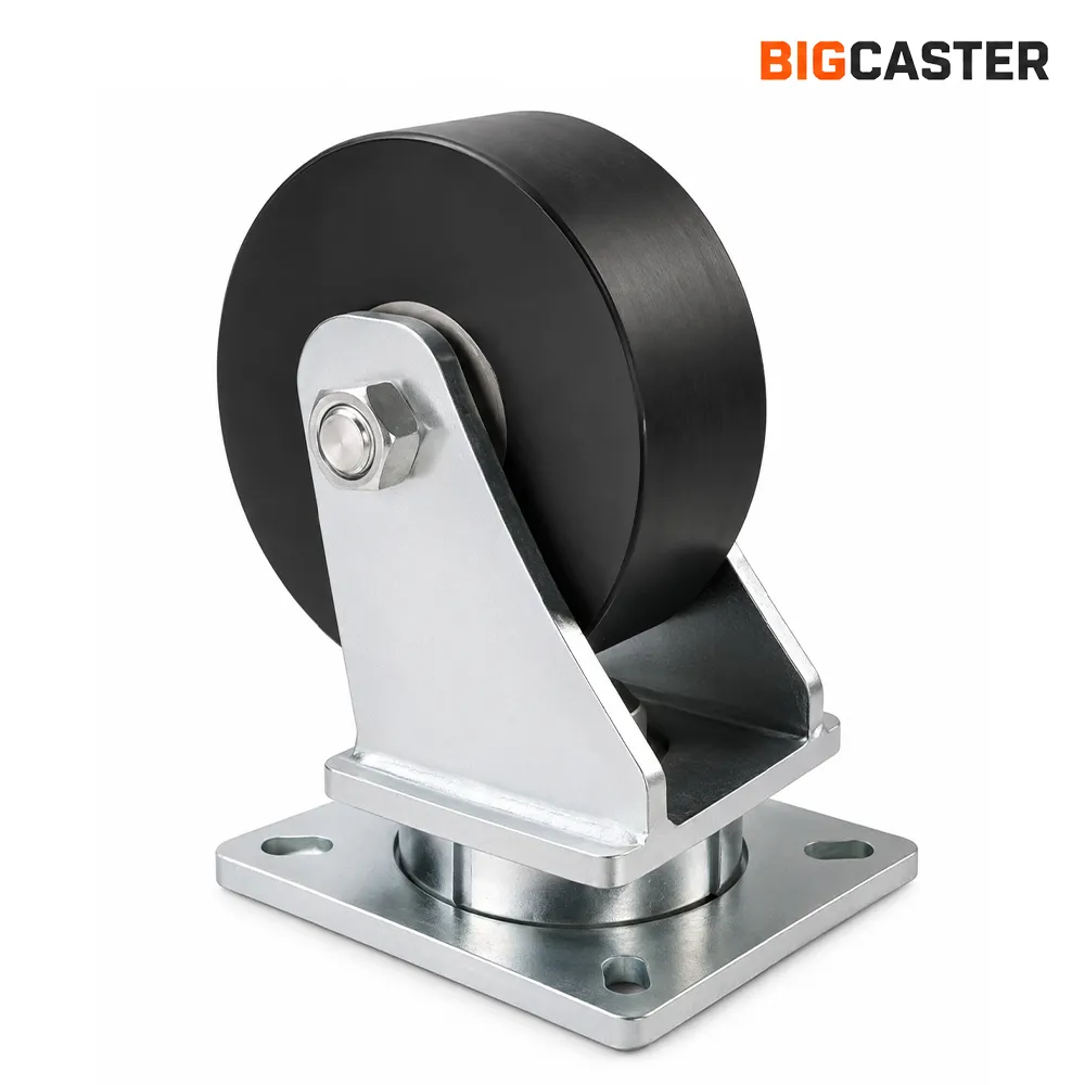
| Nominal wheel size | Wheel diameter | Overall caster height | Swivel radius | Rated load per caster |
|---|---|---|---|---|
| 6 inch | 150 mm | 214 mm | 114 mm | 2,000 kg |
| 8 inch | 200 mm | 264 mm | 148 mm | 2,500 kg |
| 10 inch | 250 mm | 317 mm | 184 mm | 3,000 kg |
| 12 inch | 300 mm | 367 mm | 218 mm | 3,000 kg |
This specific product series demonstrates three important principles.
Capacity may rise with diameter
The 6-, 8- and 10-inch versions increase from 2,000 kg to 3,000 kg per caster. The larger wheel and associated construction allow higher published capacity within the series.
Capacity may reach a plateau
The 12-inch model retains the 3,000 kg rating of the 10-inch model. Diameter increased, but the rated capacity did not. Another component or product-design limit governs the complete assembly.
Height and swivel space continue to grow
Moving from 6 to 12 inches increases overall caster height by 153 mm and swivel radius by 104 mm. The 12-inch wheel may roll and cross obstacles better, but it needs substantially more installation space and raises the equipment mounting surface.
These values apply to E0601. They should not be transferred to polyurethane, steel, dual-wheel or another caster series. Always compare the current product drawing and application-specific rating.
5. How Wheel Diameter Changes Overall Caster Height
Increasing wheel diameter normally increases overall caster height because the mounting surface must remain above the wheel and swivel structure.
This affects more than the underside of the equipment.
Working and loading height
A larger caster can raise:
- Cart deck height
- Operator work surface
- Machine interface points
- Loading and unloading height
- Tow-bar or hitch height
- Conveyor or production-line alignment
An extra 50 or 100 mm can make a cart incompatible with an existing workstation even if the caster performs better.
Replacement compatibility
When replacing a caster, compare actual overall height. If one replacement position is higher than the others, the frame may rock or distribute load incorrectly. Replacing all casters with a taller model can still change stability, loading interfaces and operator ergonomics.
Ground clearance
A larger wheel often improves ground clearance beneath the frame. This can protect equipment from debris or ramps, but too much clearance may be unnecessary if it creates an unstable or inconvenient height.
When low profile matters more than diameter
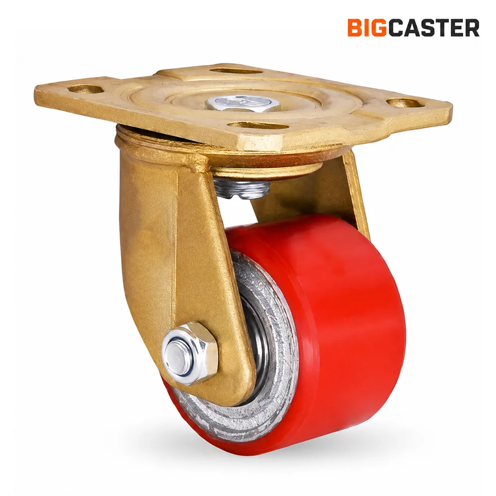
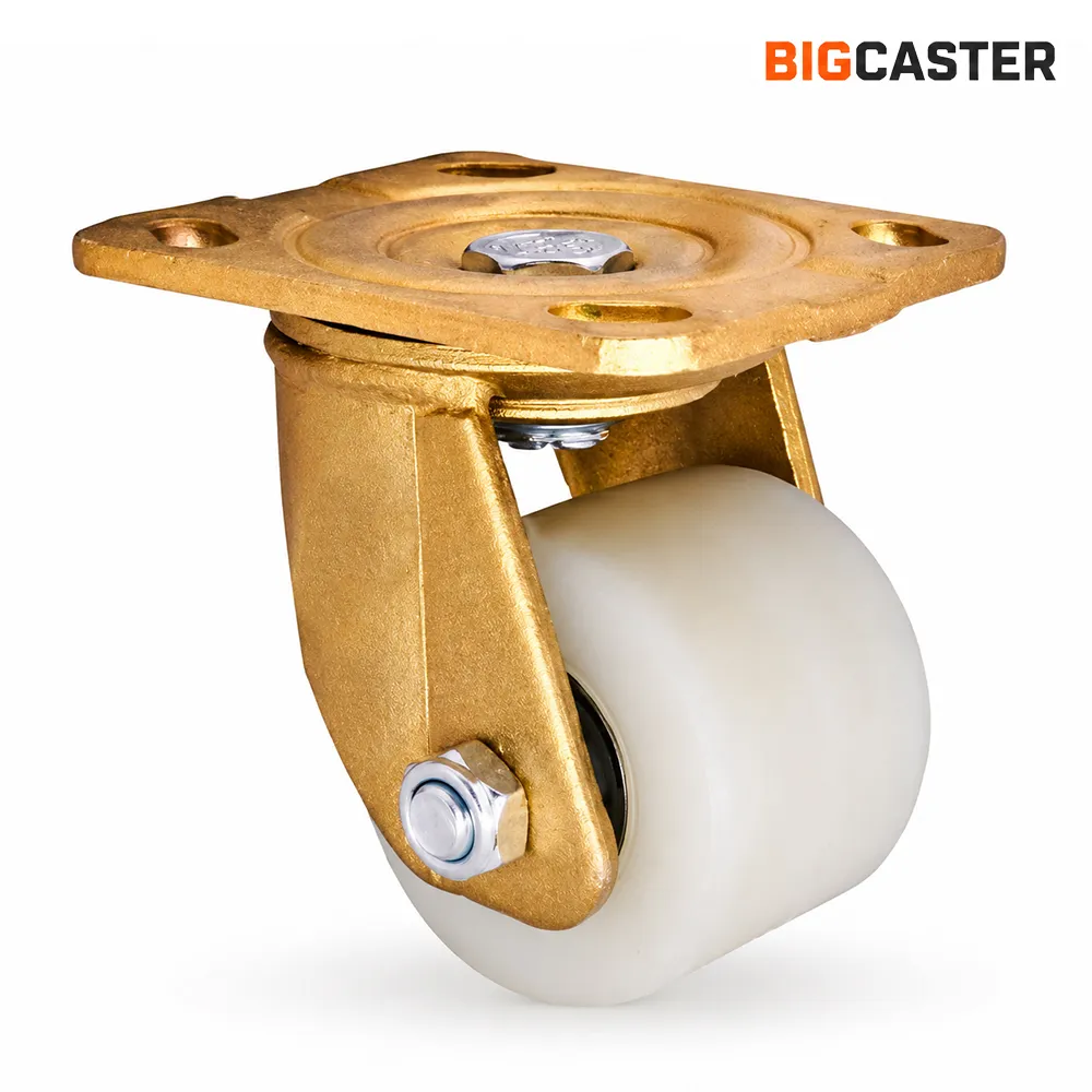
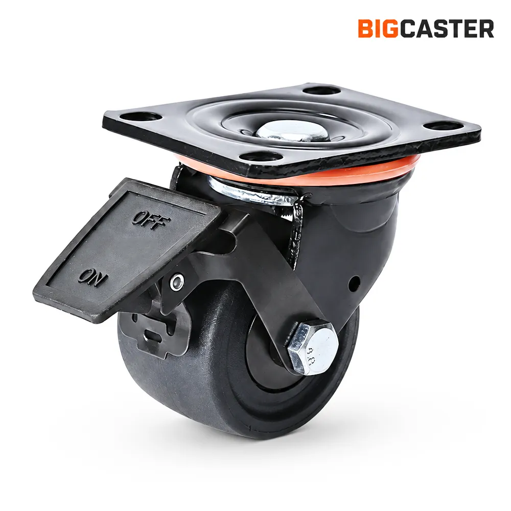
Some mold carts and heavy machines require high capacity with minimal installation height. A smaller dual-wheel or specialized low-profile caster may be more suitable than a large single wheel.
Browse BigCaster’s low profile caster range when height is the governing design constraint. The route should then be kept smooth because the smaller wheel has less favorable obstacle geometry.
6. Wheel Diameter and Equipment Center of Gravity
If larger casters raise the frame, they usually raise the equipment and its load. This can increase the center-of-gravity height relative to the floor.
Equipment stability depends on:
- Track width between left and right caster positions
- Wheelbase between front and rear positions
- Center-of-gravity height and horizontal location
- Load movement or sloshing
- Floor slope
- Turn speed
- Acceleration and braking
- Swivel-caster orientation
- Frame deflection
A large diameter wheel is not inherently unstable. A wide, low platform can remain stable on large casters. The risk appears when diameter is increased without reviewing the complete equipment geometry—especially on narrow, tall or top-heavy machines.
Potential consequences include:
- Lower tipping margin during turns
- Greater lateral load transfer on a slope
- More movement of a suspended or offset payload
- Higher forces during abrupt stops
- Difficulty fitting leveling feet or stabilizers
Where stability is critical, compare the center of gravity and support polygon before and after the height change. Conduct an engineering review for slopes, powered movement and equipment operating near personnel.
7. Wheel Diameter, Swivel Radius and Clearance
A swivel caster needs enough room for the wheel and fork to rotate through 360 degrees. Increasing diameter typically increases the swept envelope.
Check interference with:
- Equipment frame members
- Guards and covers
- Leveling feet
- Floor locks
- Tow bars
- Brakes and pedals
- Electrical cables
- Hydraulic lines
- Adjacent casters
- Bumpers and skirts
Do not check only the caster’s straight-ahead width. The wheel may swing under a frame rail or move outside the equipment footprint during a turn.
Why diameter cannot predict swivel radius exactly
Two 8-inch swivel casters can have different radii because of:
- Caster offset
- Fork design
- Single- or dual-wheel width
- Brake mechanism
- Swivel-bearing diameter
- Wheel axle position
Use the manufacturer’s drawing. If the drawing lists only one radius, confirm whether it includes the brake pedal or other protruding option.
Turning space for the entire equipment
The caster’s swivel radius is only one part of equipment maneuverability. A layout with two rigid and two swivel casters behaves differently from four swivel casters. Wheelbase, caster orientation and directional locks influence the path.
Larger wheels may reduce straight rolling force while the equipment still needs more aisle space because its caster layout and frame are unchanged.
8. Wheel Diameter and Mounting Loads
A larger caster may be heavier and place its contact forces farther from the equipment mounting plane. Changes in overall height, offset and wheel mass can alter moments at the top plate and frame.
Review:
- Mounting-plate size and thickness
- Bolt pattern and hole diameter
- Fastener grade and tightening method
- Frame-plate thickness
- Welds and reinforcement
- Side and impact loads
- Caster offset
- Towing forces
- Brake reaction forces
Matching bolt holes do not prove that a larger caster is a direct structural replacement. A taller caster can create different leverage during impact or side loading.
The complete mounting interface should be reviewed whenever wheel diameter, caster height or swivel geometry changes significantly.
9. Wheel Diameter, RPM and Powered Towing
At a given linear speed, a larger wheel rotates fewer times per minute.
Where:
- (v) is travel speed in meters per second
- (D) is wheel diameter in meters
- (RPM) is wheel revolutions per minute
At 4 km/h, or approximately 1.11 m/s:
| Nominal diameter | Approximate wheel RPM at 4 km/h |
|---|---|
| 6 in / 152 mm | 139 RPM |
| 8 in / 203 mm | 104 RPM |
| 10 in / 254 mm | 84 RPM |
| 12 in / 305 mm | 70 RPM |
Lower RPM can reduce the number of bearing and tread cycles over a given period, and the larger wheel can reduce obstacle severity. These are useful dynamic advantages.
They do not establish a higher allowable towing speed. Powered towing also depends on:
- Tread compound and heat generation
- Tread-to-core bond
- Bearing type, seals and lubrication
- Wheel balance and runout
- Swivel geometry
- Caster flutter or shimmy
- Wheel alignment
- Route impact
- Equipment steering and braking
- Duty cycle and rest periods
A heavier large-diameter wheel can also have greater rotational inertia. At high speed, imbalance and sudden directional changes may create additional forces.
Use a manufacturer-approved dynamic rating and validate the complete caster at the proposed speed. Do not infer towability from RPM or static capacity alone.
10. Does a Larger Wheel Reduce Floor Pressure?
Not necessarily. Floor pressure depends more directly on vertical load and actual contact area.
Contact area is influenced by:
- Wheel material and hardness
- Tread profile
- Wheel width
- Load
- Tread deformation
- Floor compliance
- Single- or dual-wheel structure
A larger resilient wheel may create a longer contact patch or deform differently, but diameter alone does not guarantee lower pressure. A large hard steel wheel can still concentrate high stress on a narrow band. A smaller polyurethane dual-wheel caster may spread load across two resilient contact regions.
Evaluate diameter together with material and width. The detailed trade-offs among polyurethane, nylon, cast iron, steel and rubber are covered in Best Wheel Materials for Extra Heavy Duty Casters.
Wheel Diameter Does Not Replace Wheel Material Selection
The same diameter can behave very differently depending on tread or wheel material.
Polyurethane
A large polyurethane wheel can improve obstacle crossing and rolling leverage while offering more floor protection than metal. Its compound, tread thickness, heat buildup and bond still require review.
PA and MC nylon
A large nylon wheel combines favorable obstacle geometry with a hard, low-deformation contact surface. It may roll efficiently on smooth floors but transmit noise and shock at joints.
Cast iron and steel
Increasing diameter can make an obstacle less severe relative to the wheel, but the contact remains hard. Floor pressure, noise, impact transfer and corrosion must still be checked.
Rubber
A larger rubber wheel may improve ride and obstacle crossing. Rubber deformation, starting force, flat spotting and verified capacity remain important under an extra heavy load.
Wheel diameter and material should therefore be selected together, then checked against the complete caster rig.
6 vs 8 vs 10 vs 12 Inch Extra Heavy Duty Caster Wheels
The following table provides a general selection direction. It is not a universal capacity chart.
| Nominal size | General selection direction | Main advantage | Main limitation |
|---|---|---|---|
| 6 inch | Height-restricted industrial equipment on controlled floors | Compact overall height | Less favorable at larger joints and debris |
| 8 inch | Balanced industrial applications | Good compromise among height, rollability and availability | Route and push force still require review |
| 10 inch | Heavy equipment on less-perfect floors or longer routes | Better obstacle geometry and lower RPM | Higher caster and swivel envelope |
| 12 inch | Demanding routes or very heavy mobile equipment with sufficient space | Strong rolling and obstacle-crossing direction | Substantial height, radius, weight and cost |
When a 6-inch wheel makes sense
A 6-inch wheel can fit industrial machinery where overall height and swivel clearance are limited. It may provide excellent capacity in an appropriate MC nylon, polyurethane, steel or dual-wheel construction.
The route should be relatively smooth. Frequent expansion joints or debris can create higher force and impact than they would for a larger wheel.
Buyers can browse BigCaster’s 6-inch caster options after confirming that the route and push-force target are compatible.
When an 8-inch wheel is a practical balance
An 8-inch wheel often provides a useful compromise: materially better obstacle geometry than a 6-inch wheel without the height and swivel radius of a 10- or 12-inch design.
It can suit industrial platforms, machines and carts on typical factory concrete. The actual decision still depends on material, capacity, joints and movement frequency.
Review available 8-inch caster configurations by complete specifications rather than size alone.
When to consider a 10-inch wheel
A 10-inch wheel is a strong direction when the equipment travels more frequently, crosses meaningful joints or needs lower wheel RPM. It also provides more space for substantial cores, hubs and bearings in some product series.
The equipment must accept the higher mounting surface and larger swept envelope. Compare 10-inch caster wheels for heavy equipment with the actual frame and route.
When to consider a 12-inch wheel
A 12-inch wheel can provide excellent geometry for rougher floors, gaps and long routes. It is useful where equipment size and height permit a large assembly.
Do not choose 12 inches solely because it is the largest standard tag. Capacity may not increase beyond a 10-inch version, as the E0601 example shows. A 12-inch caster can also be heavier, more expensive and harder to package.
Browse 12-inch industrial caster options only after confirming height, stability, radius and mounting requirements.
What about 4- and 5-inch extra heavy duty casters?
Extra heavy duty performance is not limited to 6 inches and above. A smaller hard wheel, dual-wheel assembly or reinforced low-profile caster can provide high capacity within a compact height.
Four-inch caster options and 5-inch caster options may suit mold carts, machinery and other height-restricted equipment. Their compact geometry makes route control more important. They should not be expected to cross the same obstacles as a 10- or 12-inch wheel with equal effort.
Recommended Wheel Diameter by Operating Condition
| Operating condition | Initial diameter direction | Reason | Main verification |
|---|---|---|---|
| Smooth floor with strict height limit | 6 or 8 inch, or smaller low-profile design | Compact installation | Capacity, push force and joint dimensions |
| Frequent manual movement | Largest practical diameter | Lower rolling and obstacle demand | Operator force and swivel effort |
| Frequent 10 mm expansion joints | Compare 8, 10 and 12 inch | Larger diameter improves obstacle ratio | Full-load route test and equipment height |
| Powered towing | Application-specific larger wheel | Lower RPM and improved obstacle geometry | Dynamic rating, heat and flutter |
| Low-profile mold cart | Smaller dual wheel or low-profile caster | Controls deck height | Floor pressure, capacity and steering |
| Rough concrete | 10- or 12-inch direction | Better obstacle crossing | Tread, impact, width and clearance |
| Tight space beneath equipment | Smaller diameter may be required | Reduced height and swivel radius | Rolling force and route condition |
| Tall or top-heavy machine | Diameter limited by stability review | Avoid unnecessary center-of-gravity increase | Support polygon and tipping assessment |
| Machine repositioned only for maintenance | Capacity and flat spotting may dominate | Travel performance is secondary | Parking time, tread and route |
“Initial direction” is deliberate. A 10-inch nylon wheel and a 10-inch polyurethane wheel can produce different push force, shock and floor behavior. Select a candidate diameter, then validate the complete product.
Worked Example 1: Heavy Machine Crossing Expansion Joints
Consider an industrial machine with:
- Maximum loaded weight: 8,000 kg
- Four caster positions
- Manual low-speed movement
- Smooth concrete with recurring 10 mm vertical joints
- Enough installation height for a 10-inch caster
- Need for reasonable floor protection and low noise
Step 1: Confirm capacity
Calculate the required capacity per caster using the effective supporting count and appropriate application allowance. Do not divide by four automatically if an uneven floor can leave one caster lightly loaded.
Step 2: Compare obstacle geometry
From the idealized table:
- 6-inch wheel: (F/W) approximately 0.57
- 8-inch wheel: (F/W) approximately 0.48
- 10-inch wheel: (F/W) approximately 0.42
The 10-inch direction has a meaningful geometric advantage over the same joint.
Step 3: Compare equipment consequences
The larger wheel raises overall height and increases swivel radius. The designer must check working height, center of gravity, frame clearance and mounting forces.
Step 4: Select material and configuration
Polyurethane may balance noise and floor protection. MC nylon may reduce tread deformation but transmit more impact. A dual wheel may help capacity or turning within a limited height.
Step 5: Test under load
Measure breakaway force, continuous push force, joint-crossing force and swivel effort with representative casters. Inspect the floor, tread, fasteners and bearings after repeated crossings.
The 10-inch wheel is a strong initial direction, not an automatic final answer.
Worked Example 2: Low-Profile Mold Cart
Now consider a multi-ton mold cart that:
- Moves infrequently
- Operates on a smooth, controlled route
- Must maintain a very low deck height
- Has adequate width for dual-wheel casters
- Does not cross substantial floor joints
A 12-inch wheel would provide favorable rolling geometry, but its height could make the cart unusable or raise the mold’s center of gravity excessively.
A 4- or 5-inch dual-wheel MC nylon or steel caster may package the necessary load into a lower height. The design accepts weaker obstacle-crossing performance in exchange for a low deck.
The project should then control:
- Route cleanliness
- Joint size
- Travel speed
- Floor strength
- Loaded swivel force
- Brake operation
- Wheel and bearing inspection
This example shows why the largest wheel is not always the best caster wheel size for heavy equipment.
12 Common Caster Wheel Diameter Selection Mistakes
- Assuming a larger wheel always carries more load. Capacity comes from the complete caster assembly.
- Using wheel diameter as overall caster height. The fork and swivel structure add substantial height.
- Choosing the smallest wheel that meets the rating. Capacity alone does not describe obstacle crossing or push force.
- Choosing the largest available wheel without checking equipment geometry. Height, stability and swivel clearance may become unacceptable.
- Ignoring swivel radius. A caster can fit vertically and still strike the frame while rotating.
- Ignoring center-of-gravity change. Raising tall or narrow equipment can reduce tipping margin.
- Using one obstacle-to-diameter rule for every route. Tread, speed, load and obstacle shape change the result.
- Claiming that a large wheel eliminates impact. Dynamic shock remains at speed and on severe floors.
- Treating rolling and swivel resistance as the same. Diameter affects them through different mechanisms.
- Inferring towing speed from lower wheel RPM. Dynamic capacity, heat and caster stability still govern.
- Using diameter to compensate for the wrong wheel material. A large steel wheel remains hard on the floor; a large soft wheel can still deform.
- Skipping a full-load route test. Real equipment behavior cannot be predicted from nominal size alone.
Heavy Duty Caster Wheel Diameter Worksheet
| Required information | Project requirement |
|---|---|
| Equipment description | |
| Maximum loaded equipment weight | |
| Number of caster positions | |
| Effective supporting caster count | |
| Required capacity per caster | |
| Manual, powered or towed movement | |
| Normal and maximum speed | |
| Travel distance and cycles | |
| Floor material and condition | |
| Largest step or obstacle height | |
| Largest gap width | |
| Joint-crossing frequency | |
| Desired wheel material | |
| Current wheel diameter | |
| Candidate wheel diameters | |
| Wheel width | |
| Single- or dual-wheel configuration | |
| Maximum overall caster height | |
| Required ground clearance | |
| Maximum swivel radius | |
| Equipment center-of-gravity height | |
| Push-force target | |
| Mounting plate and bolt pattern | |
| Brake or directional lock | |
| Required validation testing |
Information to Send BigCaster
For a useful wheel-diameter recommendation, provide:
- Maximum loaded equipment weight
- Number and location of casters
- Center-of-gravity information
- Current caster model and diameter, if replacing
- Maximum overall caster height
- Available swivel space
- Mounting plate dimensions and bolt pattern
- Manual, powered or towed movement
- Speed, distance and cycles per day
- Floor type and route photographs
- Measured step height, joint width and debris
- Preferred wheel material
- Floor-protection and noise requirements
- Single- or dual-wheel preference
- Current problems such as difficult pushing, impact or premature wear
- Quantity and project schedule
BigCaster can compare wheel diameter, material, bearings, mounting and configuration across its extra heavy duty caster range. Custom load capacity and installation dimensions can also be reviewed for suitable projects.
Frequently Asked Questions
Are larger caster wheels easier to push?
Usually, when load, material, bearings, width and floor are comparable. A larger radius provides more leverage against rolling resistance and makes joints or debris smaller relative to the wheel. A soft tread, poor bearing or misaligned caster can still create high force.
Does a larger caster wheel carry more weight?
It may within one product series, but diameter alone does not determine capacity. Wheel material, width, core, hub, bearings, axle, fork, swivel section and mounting plate all contribute to the complete rating.
What size caster wheel do I need for heavy equipment?
Choose by required capacity, floor obstacles, movement method, push-force target, available overall height, swivel clearance and equipment stability. The largest wheel that fits is a useful starting idea, but it must pass every other requirement.
Are 8-inch casters better than 6-inch casters?
An 8-inch wheel generally crosses the same obstacle more easily and rotates fewer times over a route. A 6-inch caster usually fits a lower, tighter installation. The better choice depends on floor condition, capacity and equipment geometry.
When should I use 10- or 12-inch caster wheels?
Consider them for frequent movement, significant joints, rougher floors or long travel distances when the equipment can accept their height and swivel radius. Do not assume the 12-inch version has a higher rating than the 10-inch version.
How does caster diameter affect rolling resistance?
A larger radius generally reduces the horizontal force associated with a given resistance moment and improves obstacle geometry. Tread deformation, bearings, load, floor and alignment also determine actual rolling resistance.
Does wheel diameter affect caster swivel radius?
Usually. A larger wheel commonly increases the swept envelope, but caster offset, fork design, wheel width and brake options also affect swivel radius. Use the product drawing.
Can I replace a 6-inch caster with an 8-inch caster?
Only after checking overall height, mounting plate, bolt pattern, capacity, swivel radius, equipment stability, ground clearance and load sharing. A larger caster is not automatically a direct replacement.
What wheel diameter is best for powered towing?
There is no fixed best diameter. Larger wheels can lower RPM and improve obstacle crossing, but the wheel, bearings, tread, swivel structure and equipment must be rated and tested for the intended speed, route and duty cycle.
Final Wheel-Diameter Selection Principle
Larger wheels generally improve the mobility of extra heavy duty equipment. They reduce obstacle severity relative to the wheel, can lower rolling effort and rotate more slowly at a given travel speed.
Those benefits come with geometric and structural costs. Overall caster height, center-of-gravity height, swivel radius, component weight and mounting moments may all increase. Load capacity may rise within a product family, but it can also reach a plateau while size continues to grow.
Use this sequence when selecting heavy duty caster wheel diameter:
- Calculate the required capacity per complete caster.
- Measure the actual route, including step height and gap width.
- Define manual or powered movement and the duty cycle.
- Establish acceptable starting, rolling and swivel force.
- Determine maximum caster height and required ground clearance.
- Review equipment center of gravity and stability.
- Confirm swivel radius and frame clearance.
- Select wheel material, width and single- or dual-wheel structure.
- Compare actual products within the same series.
- Validate the final caster under full load on the real route.
The best diameter is not simply the largest wheel or the smallest wheel that carries the load. It is the diameter that gives the equipment acceptable mobility without compromising fit, stability, structure or service conditions.