

A caster can have more than enough rated capacity and still make a machine extremely difficult to move. Load capacity answers whether the caster can support the equipment. Rolling resistance helps determine whether the equipment can be moved and controlled as intended.
For extremely heavy equipment, even a small resistance relative to the supported load can become a large absolute push or tow force. Wheel material, diameter, tread deformation, bearings, floor condition, load distribution and caster alignment all affect the result. Starting from rest and changing direction can require substantially different forces from maintaining steady travel on a smooth, level floor.
This guide explains extra heavy duty caster rolling resistance as part of a complete mobility system. It separates starting resistance, steady rolling resistance, swivel resistance, obstacle-crossing force and grade resistance; shows how to estimate level-floor and slope force; and provides a practical loaded push-pull test method.
If you already know your equipment specifications, explore BigCaster’s extra heavy duty casters. If you are still determining the required capacity per caster, begin with the Extra Heavy Duty Caster Load Capacity Guide.
Important: There is no universal “safe manual push force” for every workplace or operator. Handle position, posture, frequency, travel distance, floor, route, workforce and local ergonomic requirements all matter. Equipment that cannot be safely controlled by manual force may require a powered mover or a redesigned handling process—not simply a different wheel.
Quick Answer: What Determines Caster Rolling Resistance?
Low rolling resistance is a system result rather than one product feature. A larger wheel may reduce obstacle and steady rolling demand, but it can also raise the equipment and require more swivel clearance. A harder wheel may deform less on smooth concrete, yet transmit more shock into the bearings, equipment and floor.
| Factor | General effect on rolling performance | Important limitation |
|---|---|---|
| Larger wheel diameter | Usually reduces steady rolling and obstacle-crossing force under comparable conditions | Increases overall height and often swivel radius |
| Harder tread | Usually deforms less on a smooth, hard floor | Can increase noise, impact and floor damage |
| Softer tread | Improves cushioning and floor protection | Usually creates more deformation and hysteresis loss |
| Higher load | Increases total force and may increase tread deformation | The relationship may not be perfectly linear |
| Precision wheel bearings | Can reduce hub friction and maintain alignment | Bearings are only one source of system resistance |
| Smooth, hard floor | Usually supports efficient rolling | Joints, debris, slopes and contamination change the result |
| Correct caster layout | Reduces scrub and unnecessary steering corrections | The best layout depends on the route and movement pattern |
| Accurate alignment | Prevents wheels from working against one another | A distorted frame can change alignment under load |
| Suitable temperature | Keeps tread and lubricant behavior within design range | Cold, heat and continuous running can change resistance |
The best way to confirm performance is to measure starting, sustained rolling and turning forces at maximum intended load on the actual route.
Starting, Rolling and Swivel Resistance Are Not the Same
The phrase “caster rolling resistance” is often used loosely, but industrial equipment experiences several different forces.
| Force or resistance | When it occurs | What it describes | Major influences |
|---|---|---|---|
| Starting resistance | Equipment begins moving from rest | Peak or initial force required to create motion | Dwell time, tread set, bearing condition, caster direction, load and floor |
| Rolling resistance | Equipment travels steadily | Force required to maintain approximately constant speed on a defined surface | Tread hysteresis, diameter, load, bearings, floor and alignment |
| Swivel resistance | A swivel caster changes direction | Force needed to rotate the fork and reorient the wheel | Swivel bearing, load, swivel offset, tread friction, wheel width and layout |
| Obstacle-crossing force | Wheel reaches a joint, threshold or debris | Transient force needed to lift and move the wheel over an obstruction | Wheel diameter, obstacle geometry, speed, load and tread |
| Grade resistance | Equipment travels on a slope | Component of weight acting along the slope | Total weight and slope angle |
| Acceleration force | Equipment changes speed | Force required to accelerate its mass | Total mass and acceleration rate |
Starting resistance
Starting resistance must be overcome before a stationary wheel begins to roll. It can exceed steady rolling resistance because:
- A resilient tread may have deformed while parked.
- Lubricant and seals have not yet reached moving conditions.
- Swivel casters may be pointing in different directions.
- Wheel bearings or swivel bearings may need to move away from a loaded stationary contact position.
- Static floor contamination or brake drag may be present.
- The operator or tow device must accelerate the equipment mass.
Some general guides use a multiple of steady rolling force to estimate starting force. That should not be treated as a universal rule for extra heavy duty casters. Dwell time, temperature, tread material, caster orientation and route can make the ratio very different. Measure the actual starting peak when it is important.
Steady rolling resistance
Steady rolling resistance is the opposing force while equipment travels at approximately constant speed on a defined surface. The most important source in a resilient wheel is often energy loss as the tread compresses and recovers through the contact patch.
This is the most controlled value in a laboratory test, but it is not necessarily the highest force the equipment will encounter in service.
Swivel resistance
Swivel resistance is the force needed to rotate a caster fork around its vertical axis. It includes swivel-bearing friction and the force required to move or scrub the loaded wheel contact patch into a new direction.
An equipment base can therefore roll easily in a straight line but be difficult to turn. This is common when several heavily loaded swivel casters start in conflicting directions.
Obstacle-crossing force
A floor joint or threshold creates a transient geometric barrier. The wheel center has to rise as it passes the obstacle. This is not simply an increase in steady rolling resistance.
A route with acceptable level-floor rolling force can still produce a dangerous peak at a sharp joint. Wheel diameter and obstacle geometry should be evaluated separately.
Grade resistance
On a slope, part of the equipment weight acts in the downhill direction. Even casters with very low rolling resistance may require substantial uphill force or braking control. Slope travel also changes stability and stopping requirements.
What Is Rolling Resistance?
An ideal, perfectly rigid wheel on a perfectly rigid, level surface with frictionless bearings would roll without energy loss. Real caster wheels and floors are not ideal.
As a loaded wheel enters the contact area:
- The tread or wheel material deforms.
- The floor may also deform.
- Material within the contact zone experiences internal stress.
- The wheel recovers as it leaves the contact area.
- Not all deformation energy is returned.
The lost energy is commonly associated with hysteresis. Softer materials generally deform more, but hardness alone does not determine hysteresis. Compound chemistry, rebound resilience, tread thickness, temperature, load and speed all matter.
Additional resistance comes from:
- Wheel bearings and seals
- Swivel bearings during direction changes
- Hub and axle misalignment
- Wheel scrub
- Brake drag
- Floor roughness and debris
- Wheel or floor indentation
- Structural flex in the equipment
Rolling resistance vs sliding friction
Rolling resistance should not be confused with the coefficient of sliding friction.
When a wheel rolls straight without slipping, the primary losses are related to deformation, bearing friction and small internal movements. During a stationary swivel or forced side movement, the tread may slide or scrub across the floor. Sliding friction then becomes a major part of the steering force.
This distinction explains why a tread with good traction can roll efficiently in a straight line but resist a loaded pivot.
Rolling resistance vs push force
The force measured at a handle or tow point is a system force. It can contain:
- Wheel rolling resistance
- Bearing friction
- Swivel alignment force
- Tread scrub
- Slope force
- Acceleration force
- Obstacle force
- Brake drag
- Forces from frame and caster misalignment
Calling every measured force “rolling resistance” hides the cause and can lead to the wrong corrective action.
Why Rolling Resistance Matters More at Extra Heavy Loads
Resistance is often discussed as a small fraction of supported load. Under several tonnes of equipment, that small fraction can still produce hundreds or thousands of newtons of force.
This creates four practical concerns.
Operator capability
An equipment base may be technically movable but exceed acceptable manual push, pull or steering demand. High starting peaks are particularly difficult because the operator must generate force before the equipment provides any motion feedback.
Stopping and control
Reducing rolling resistance makes equipment easier to move, but it can also make it easier to continue moving. Brakes, floor slope, operator position and stopping procedure must remain adequate.
Powered mover sizing
A tug or powered handle must overcome steady rolling, slope, acceleration, turning and route peaks. Sizing it from level-floor rolling resistance alone can produce an underpowered system.
Component life
High push force may indicate tread deformation, overloaded bearings, poor alignment or a damaged caster. Continued movement can turn a mobility problem into premature component or floor failure.
The caster with the highest catalog load rating is therefore not necessarily the caster that creates the best mobile equipment. Capacity and mobility have to be evaluated together.
1. Wheel Material and Tread Deformation
Wheel material is one of the strongest influences on caster wheel rolling resistance, especially under high load.
MC nylon and PA nylon
PA nylon and MC nylon are hard engineering materials with relatively low deformation under load. On a smooth, hard industrial floor, they can provide efficient rolling and high capacity.
Possible advantages include:
- Low tread deformation
- Relatively low hysteresis loss
- Good load support
- Clean, non-marking performance in many applications
- Resistance to many oils and industrial substances
Trade-offs include:
- Limited cushioning
- Higher noise than resilient treads
- More impact transmitted through joints and debris
- Possible floor marking or concentrated floor stress
- Performance that depends strongly on floor smoothness
Explore BigCaster’s heavy duty nylon casters when low deformation on a suitable floor is a priority.
Steel and cast iron
Steel and cast iron wheels deform very little under normal working loads. On strong, smooth floors, this can result in low tread-related rolling loss.
However, low deformation is not automatically the best system choice. Metal wheels:
- Transmit strong shock into bearings and equipment
- Generate more noise
- Can mark or damage floors
- Offer little vibration isolation
- May have limited traction on some surfaces
- Require strong, clean routes
Use steel casters for applications where concentrated load capability and severe mechanical service take priority over floor protection and cushioning.
Polyurethane
Polyurethane can provide a useful balance between high load capacity, wear resistance, floor protection and rolling performance. But “polyurethane” is not one rolling-resistance value.
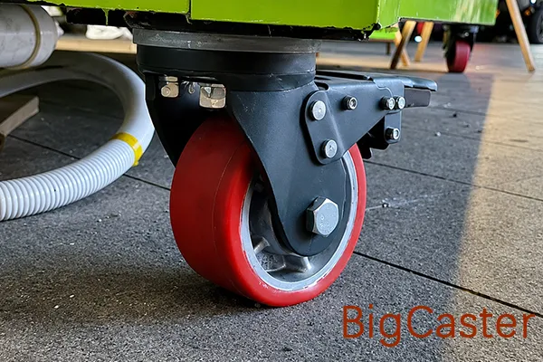
Important variables include:
- Shore hardness
- Rebound resilience
- Tread thickness
- Compound chemistry
- Wheel-core material
- Tread-to-core bond
- Temperature
- Load and speed
- Dwell time
A hard, high-rebound polyurethane can roll efficiently while protecting the floor better than bare metal. A softer or thicker tread generally deforms more and may require greater sustained force, although it can reduce shock and noise.
Continuous deformation also creates heat. For repeated or powered movement, confirm speed, duty cycle and temperature suitability rather than choosing by hardness alone.
See BigCaster’s polyurethane caster range for available industrial directions.
Rubber
Rubber is chosen when cushioning, traction, quiet operation and floor protection matter. Its greater deformation usually creates more hysteresis loss than harder nylon or metal wheels under comparable heavy loads.
That trade-off may still be appropriate for:
- Rougher floors
- Noise-sensitive areas
- Equipment sensitive to vibration
- Applications needing grip
- Floors that cannot tolerate hard wheel contact
The correct comparison is not simply “rubber has higher resistance.” It is whether its cushioning reduces damaging impacts and improves total application performance enough to justify the additional push force. Review BigCaster’s rubber caster range when cushioning and noise control are important.
Material comparison
| Wheel material | Typical deformation on a hard floor | General rolling direction | Main trade-off |
|---|---|---|---|
| Steel or cast iron | Very low | Efficient on suitable smooth, strong floors | Noise, impact and floor damage |
| MC nylon or PA nylon | Low | Often low resistance on smooth, hard floors | Vibration and limited cushioning |
| Hard, high-rebound polyurethane | Moderate | Balanced industrial performance | Compound, heat and load dependent |
| Softer polyurethane | Higher | More cushioning with potentially higher force | Deformation and heat buildup |
| Rubber | Higher | Generally higher resistance under heavy load | Quiet movement, traction and shock absorption |
This table describes general trends, not product-specific test results. Wheel diameter, width, bearing, floor and load can reverse a simplistic material ranking.
For a complete environmental and material comparison, read Best Wheel Materials for Extra Heavy Duty Casters.
2. Wheel Diameter
Increasing wheel diameter is one of the most effective ways to improve heavy equipment mobility when installation height permits.
For the same load, material and floor, a larger wheel generally:
- Deforms over a longer contact geometry
- Encounters a floor irregularity as a smaller fraction of its radius
- Requires less force to climb a given sharp obstacle
- Rotates at lower RPM at the same travel speed
- Bridges small depressions more effectively
The trade-offs include:
- Greater overall caster height
- Larger swivel envelope
- Higher equipment mounting surface
- Potential change in center-of-gravity height
- More component weight and cost
Wheel diameter can have a larger practical effect than changing the wheel-bearing type when the main problem is floor joints or debris. Bearings reduce internal friction; they do not change the geometry of climbing an obstacle.
The full size analysis is covered in How Wheel Diameter Affects Extra Heavy Duty Caster Performance.
3. Load on Each Wheel
As load increases, total rolling force usually increases. In resilient treads, deformation may also increase, changing the resistance per unit of load.
Load may not be distributed equally
On a rigid four-caster frame, an uneven floor can place most of the load on three positions. An offset center of gravity can overload one side. In a six-caster rocker layout, the center wheels may intentionally carry a dominant share.
One overloaded wheel can deform more, heat more and create disproportionate resistance. The equipment may feel difficult to move even when the sum of all catalog capacities exceeds total weight.
Capacity reserve is not a rolling-force guarantee
A caster with a large capacity reserve may remain structurally safe, but its tread can still produce significant rolling resistance. Conversely, a hard metal wheel may roll efficiently but be unsuitable for the floor.
Calculate the effective load at each position before comparing mobility. Use the caster wheel load capacity calculator for initial screening, then account for the actual center of gravity, frame and floor.
4. Wheel Bearings
Wheel bearings allow the wheel to rotate around its axle. Bearing friction is usually only one portion of total caster rolling resistance, but damaged or incorrectly installed bearings can dominate the result.
Resistance can increase because of:
- Raceway or rolling-element damage
- Contamination
- Corrosion
- Incorrect internal clearance
- Excessive axle clamping without correct spacer support
- Bent axle or misaligned fork
- Hardened, missing or incompatible lubricant
- Contact-seal drag
- Load or speed beyond the bearing application
Ball bearings and high-load support
Precision ball bearings can provide efficient rolling and controlled wheel alignment. BigCaster E-series products may increase from two to four bearings per wheel to support higher hub loads.
The additional bearings do not automatically reduce rolling resistance or double capacity. They create more bearing support in the hub, while seals, preload, bearing size and load sharing still affect friction. The complete wheel, axle and caster rating remains the controlling specification.
Do not use an unloaded spin test as proof
A wheel that spins for a long time while unloaded may perform poorly under several tonnes because tread deformation and bearing contact load are absent from the hand test. A sealed bearing may stop sooner when unloaded but remain better protected in real service.
For the two separate bearing systems inside a caster, read Extra Heavy Duty Caster Bearings Explained.
5. Swivel Bearings and Swivel Resistance
Swivel bearings do not control forward wheel rotation. They allow the fork to rotate beneath the mounting plate.
A conventional heavy duty swivel head commonly uses upper and lower groups of steel balls. In BigCaster extra heavy duty swivel designs, an upper ball-bearing structure works with a lower flat tapered bearing to strengthen load support and impact resistance.
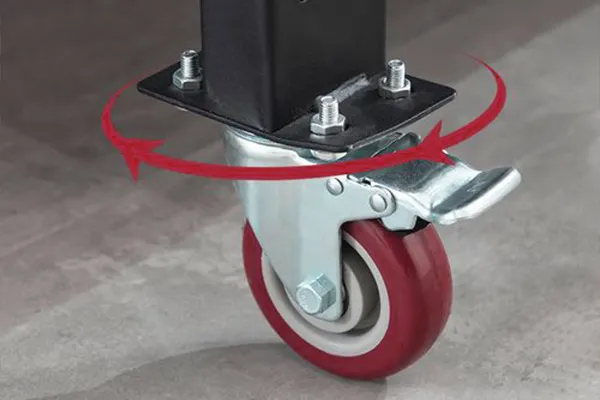
That structure should not be advertised as automatically producing the lowest steering force. Swivel resistance also depends on:
- Vertical load
- Swivel offset
- Wheel diameter and width
- Tread material
- Contact patch
- Floor friction
- Bearing preload and lubrication
- Caster orientation
- Equipment layout
Swivel offset
Swivel offset is the horizontal distance between the vertical swivel axis and wheel axle. It creates a trailing action that helps the wheel align with movement. Too little or too much offset for the load and application can change steering response, swept radius and structural moment.
Stationary swiveling and scrub
When equipment changes direction without meaningful forward travel, the loaded tread may have to scrub across the floor. A wide, soft wheel can resist this movement even if its forward rolling resistance is acceptable.
Directional change should therefore be measured separately from straight rolling.
6. Floor Surface
Laboratory rolling-resistance values are usually collected on a controlled surface. Real industrial floors introduce additional loss and peak forces.
Smooth, hard concrete
A clean, level, smooth concrete floor generally supports efficient rolling. Hard nylon, steel and high-capacity polyurethane wheels can all perform well when the floor is strong enough.
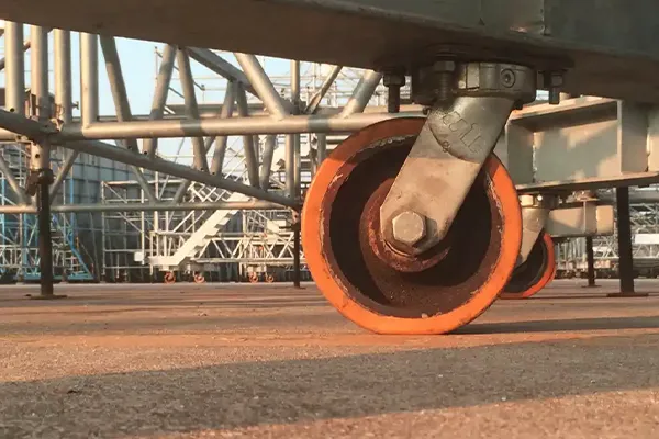
Check for:
- Expansion joints
- Cracks
- Coatings
- Oil or water
- Sand, chips or fasteners
- Local slopes
Rough concrete
Rough concrete creates continuous small vertical movements. Hard wheels may roll with low tread hysteresis but transmit strong vibration and impact. Resilient wheels reduce shock but deform more.
Larger diameter is often more useful than selecting an extremely hard small wheel.
Soft or resilient flooring
The floor itself can deform under concentrated wheel load. A narrow hard wheel may sink into or damage the surface. A wider wheel reduces floor pressure but can increase contact area and swivel scrub.
The best configuration balances:
- Wheel deformation
- Floor deformation
- Contact pressure
- Steering behavior
- Floor protection
Steel plates and rails
Metal wheels on steel plates can provide very low deformation, but alignment and surface condition become critical. Small debris can create severe point impact. Rail-guided wheels introduce different contact and steering conditions from free-rolling casters.
Floor joints and thresholds
A sharp joint should be treated as an obstacle, not as ordinary rolling resistance. Measure its height, width and edge shape. A gap can be more severe than a rounded bump of the same nominal height.
7. Wheel Width and Contact Patch
A wider wheel distributes load over a larger nominal tread width, but this does not guarantee lower rolling force.
On a hard floor:
- More tread volume may deform.
- The contact patch may produce more scrub during turns.
- Manufacturing variations can create uneven contact across the width.
On a soft floor:
- Greater width can reduce sinking.
- Lower surface pressure can protect the floor.
- The reduction in floor deformation may outweigh added wheel deformation.
Wheel width should therefore be chosen with the floor and movement pattern, not from load capacity alone.
8. Temperature and Dwell Time
Temperature changes the behavior of tread materials, seals and lubricant.
Low temperature
Some resilient materials become harder in the cold. This may reduce deformation but increase impact and reduce rebound performance. Lubricant can also become more viscous, increasing bearing resistance.
High temperature
Heat can soften tread materials, reduce capacity, accelerate bond degradation and change grease behavior. Continuous rolling produces cyclic deformation heat in polyurethane and rubber treads.
Long dwell time
When heavily loaded equipment remains stationary, a resilient tread may temporarily take a set at the contact patch. The first movement after a long dwell can require greater force until the wheel recovers.
For this reason, test both:
- A cold start after the maximum expected stationary period
- Warmed steady travel after repeated movement
9. Alignment, Mounting and Brake Drag
Incorrect installation can cancel the advantages of a well-designed wheel.
Rigid casters must be parallel
Two rigid casters pointing in slightly different directions force at least one wheel to scrub. At extreme loads, a small angular error can create large side force.
Mounting surfaces must be coplanar
Twisted or uneven mounting surfaces change caster load distribution. One wheel may carry far more load than expected while another is lightly loaded.
The frame can distort under load
A frame that is aligned while empty may deflect after loading. Measure or verify caster orientation at operating weight.
Brakes must release fully
A wheel brake, total lock or floor lock that remains partially engaged creates drag and heat. Confirm pedal travel and clearance through the caster’s full swivel range.
Axles and forks must remain straight
A bent axle can misalign wheel bearings and cause tread contact to shift. A spread or twisted fork can create similar problems.
10. Caster Layout
Caster layout determines whether wheels can follow the intended direction or are forced to scrub.
Two swivel and two rigid casters
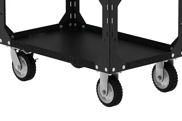
This common arrangement provides a defined straight-travel direction. The rigid pair helps the equipment track while the swivel pair steers.
It often works well for:
- Long aisles
- Frequent straight travel
- Manual carts with conventional turns
- Routes that do not require lateral translation
Turning requires an arc and adequate space.
Four swivel casters
Four swivel casters allow lateral and multidirectional movement. However, when starting from rest, they may point in four different directions. The initial force has to align them while the treads roll or scrub under load.
An all-swivel platform may also require continuous correction during long straight travel.
Directional locks
Directional locks allow selected swivel casters to behave like rigid positions while the wheels continue rolling. They can combine multidirectional positioning with controlled straight travel.
The locks must engage in a common intended direction. Incorrectly oriented locks can make equipment more difficult or impossible to move safely.
Six or more casters
Multi-caster platforms can create complex load sharing and scrub. If all wheels cannot follow compatible paths during a turn, adding casters may increase resistance rather than reduce it.
Review Swivel, Rigid and Caster Layouts for Extremely Heavy Equipment before treating wheel count as a mobility solution.
Single-Wheel vs Dual-Wheel Rolling Resistance
Neither single-wheel nor dual-wheel casters always have lower rolling resistance. The result depends on diameter, tread, load, bearings, wheel spacing and floor.
Potential single-wheel advantages
- Simpler axle and hub arrangement
- Fewer tread contact zones
- Potentially less straight-line bearing and seal drag
- A larger single wheel may cross obstacles better than smaller twin wheels
- Less space between wheels for debris accumulation
Potential dual-wheel advantages
- Load is divided across two wheels within one caster position
- Each wheel may deform less than one narrower wheel carrying the full load
- Floor pressure can be distributed across more tread
- Independently rotating wheels can provide differential action during a turn
- High capacity may be achieved within a limited overall-height envelope
Potential dual-wheel limitations
- More bearings and seals
- More total tread contact
- Possible load imbalance between the two wheels
- Greater overall assembly width
- More clearance required during swiveling
- Debris accumulation between wheels
- Scrub affected by spacing and tread width
Do not compare only the number of wheels. Compare the complete loaded caster on the intended floor. The structural trade-offs are explained in Single-Wheel vs Dual-Wheel Extra Heavy Duty Casters.
How to Estimate Caster Rolling Force
Calculations are useful for screening, but only when the coefficient or measured force uses a known definition and test condition.
Method 1: Sum measured rolling force per wheel
If the manufacturer provides rolling force for each wheel at the relevant load and test condition:
Where:
- (F_{\text{steady}}) is estimated steady level-floor rolling force
- (F_{\text{rolling},i}) is the measured or specified rolling force of wheel (i)
- (n) is the effective number of loaded wheels
This estimate assumes compatible wheel alignment and a comparable floor. The complete equipment force may be higher:
Starting, swiveling and obstacle peaks should be evaluated separately.
Method 2: Dimensionless rolling-resistance coefficient
Some sources use a dimensionless coefficient (C_{rr}):
Where:
- (F_{rr}) is rolling-resistance force
- (C_{rr}) is a dimensionless coefficient
- (N) is the normal load force
On a level floor, total normal force is approximately total mass multiplied by gravitational acceleration.
Method 3: Resistance-arm coefficient with length units
Other engineering references use a rolling-resistance parameter (b) with units of length:
Where (R) is wheel radius.
These two coefficient conventions are not interchangeable. Never insert a coefficient into a formula until its units and definition are confirmed.
Grade force
For equipment of mass (m) on a slope angle (\theta):
For a small slope expressed as decimal grade (s):
A 1% grade is entered as (0.01), not (1).
Acceleration force
To accelerate equipment mass (m) at rate (a):
Simplified total force direction
For straight uphill movement without an obstacle:
This is a screening relationship, not a universal safety formula. It does not predict a sharp threshold, stationary swivel scrub or every starting peak.
Worked Example: Level Floor and a 1% Grade
Consider a hypothetical 4,000 kg equipment base. Assume that testing or validated data gives an effective dimensionless rolling-resistance coefficient of (0.020) for the complete wheel and floor combination.
This number is an example only; it is not a BigCaster product value.
Step 1: Estimate normal load
Step 2: Estimate steady level-floor rolling force
Step 3: Add a 1% grade
Step 4: Combine steady rolling and grade force
This estimate still excludes:
- Starting peak
- Acceleration
- Swivel alignment
- Brake drag
- Misalignment
- Floor joints
- Safety or design allowance
The example shows why a small slope matters under a heavy load: a 1% grade adds about half as much force as the assumed level-floor rolling resistance in this scenario.
Why Manufacturer Rolling-Resistance Data May Differ
Rolling-resistance values cannot be compared responsibly without knowing the test method.
Important variables include:
- Wheel or complete caster test
- Test surface
- Load per wheel
- Load as a percentage of rated capacity
- Wheel diameter and width
- Speed
- Ambient and wheel temperature
- New, run-in or aged wheel
- Measurement distance
- Caster orientation
- Tread compound batch
- Bearing and seal configuration
For example, controlled industry testing may use a smooth, level steel surface, a defined speed, temperature and fraction of rated load. Those conditions allow products within the same method to be compared. They do not reproduce cracked concrete, debris, slopes or a cold start after several days of parking.
Ask these questions before comparing data
- Is the value starting force or steady rolling force?
- Was a wheel or complete swivel caster tested?
- What load was applied?
- What floor was used?
- What speed and temperature were used?
- Is the result force, force per wheel or a coefficient?
- If it is a coefficient, what are its units and formula?
- Were the wheels new or run in?
- Was swivel alignment included?
- Is the published figure typical, maximum or guaranteed?
Do not rank two suppliers by isolated rolling-resistance numbers unless these conditions are comparable.
How to Perform a Loaded Push-Pull Test
A field test connects product selection with the actual equipment, floor and route.
Test equipment
Use a calibrated force gauge, load cell or suitable push-pull instrument with enough capacity for expected peaks. The fixture should measure force in the real push, pull or tow direction.
Step 1: Prepare the equipment
- Load the equipment to maximum normal operating weight.
- Place the payload in its worst credible position.
- Record center of gravity where practical.
- Confirm caster quantity and type.
- Inspect wheels, brakes, bearings and mounting bolts.
- Remove unsafe defects before testing.
Step 2: Record the environment
- Floor material and condition
- Temperature
- Route length
- Joints and obstacles
- Slope
- Wheel and caster orientation
- Time the equipment remained stationary
Step 3: Measure starting force
Apply force smoothly in the intended direction and record the peak needed to initiate useful movement. Avoid a sudden jerk unless that reflects the approved operating method.
Repeat with swivel casters in:
- The intended travel direction
- A 90-degree orientation
- A realistic random parked orientation
This shows how much caster alignment contributes to the start.
Step 4: Measure steady rolling force
Once the equipment reaches the defined low speed, record the sustained force over a smooth section. Use the same speed and distance for comparisons.
Step 5: Measure turning force
Test the actual turns required by the route:
- Gradual corner
- Tight corner
- 90-degree direction change
- Lateral positioning if permitted
- Rotation within the equipment footprint if required
Do not label turning force as steady rolling resistance.
Step 6: Measure route peaks
Record force at:
- Expansion joints
- Thresholds
- Floor transitions
- Ramps
- Cracked sections
- Docking positions
Use a safe method that does not expose personnel to an uncontrolled load.
Step 7: Repeat the test
Perform several runs and report:
- Maximum value
- Minimum value
- Typical range
- Test configuration
Do not publish only the easiest run.
Step 8: Test after dwell and continuous movement
If the equipment remains parked for long periods, repeat the starting test after the maximum expected dwell. If it travels frequently, conduct an extended run and check tread and bearing temperature.
Step 9: Evaluate control as well as force
Observe:
- Straight tracking
- Operator posture
- Visibility
- Stopping distance
- Brake accessibility
- Drift on slopes
- Sudden caster alignment
- Wheel shimmy or vibration
The lowest force is not useful if the equipment becomes difficult to control.
How to Reduce Extra Heavy Duty Caster Rolling Resistance
1. Use the largest practical wheel diameter
Increase diameter within the available height, stability and swivel-clearance limits. This is often the most effective improvement for joints and roughness.
2. Match tread material to the floor
Use a hard, low-deformation wheel on a strong, smooth floor when noise and impact are acceptable. Use a high-rebound resilient tread when floor protection and cushioning are required.
3. Correct load distribution
Locate the loaded center of gravity and verify actual wheel contact. Redistribute the payload or strengthen the frame if one caster is overloaded.
4. Select appropriate wheel bearings
Use bearing size, seals, lubricant and quantity suitable for load, speed and contamination. Correct axle, spacer and hub installation are as important as the bearing name.
5. Improve the floor and route
Repair sharp joints, remove debris and avoid unnecessary soft or damaged sections. A route improvement can be more effective than changing casters.
6. Align rigid casters
Mount rigid wheels parallel to the intended travel direction and verify alignment at operating load.
7. Choose the correct caster layout
Use two swivel and two rigid casters when straight tracking is the main requirement. Use four swivel casters only when multidirectional movement justifies the additional alignment behavior.
8. Add directional locks where appropriate
Directional locks can help an all-swivel platform track straight. Confirm lock orientation and operating procedure.
9. Eliminate brake drag
Inspect wheel brakes, total locks and floor locks. Confirm full release throughout the swivel envelope.
10. Remove debris and replace damaged components
Clean material wrapped around axles. Replace damaged bearings, flat-spotted treads, bent axles and deformed forks after identifying the cause.
11. Control speed and acceleration
High acceleration increases peak force and load transfer. Excess speed increases impact and heat. Define realistic operating limits.
12. Use powered assistance when necessary
If tested manual force or control is unacceptable, use an appropriately sized powered mover and a caster system approved for towing or powered movement.
The Lowest Rolling Resistance Is Not Always the Best Choice
An extremely hard wheel may minimize tread deformation on a smooth floor but create unacceptable consequences:
- Floor damage
- High noise
- Shock transmitted to the load
- Bearing and swivel impact
- Vibration-related equipment problems
- Poor traction
- Difficult threshold behavior if the diameter is small
The objective is not the lowest isolated laboratory number. It is acceptable starting, rolling, steering, stopping, floor and durability performance for the complete application.
Low-Resistance Caster Selection by Application
| Application | Starting direction | Main checks |
|---|---|---|
| Manually pushed heavy cart | Large diameter, low-deformation tread and efficient bearings | Starting, sustained and turning force; handle position |
| Smooth factory floor | MC nylon, PA nylon or suitable high-rebound polyurethane | Floor protection, noise and joint impact |
| Sensitive floor | Properly sized polyurethane tread | Tread deformation, contact pressure and heat |
| Rough concrete | Larger diameter with suitable resilience | Obstacle peaks, shock, heat and sustained force |
| Long-distance powered towing | Manufacturer-approved tread, bearings and swivel structure | Speed, duty cycle, heat, shimmy and impact |
| Tight-space four-swivel equipment | Controlled swivel resistance and possible directional locks | Initial alignment, scrub and operator control |
| Long industrial platform | Compatible rigid/swivel layout | Frame stiffness, wheel alignment and load distribution |
| Equipment parked for long periods | Tread resistant to compression set | Cold-start force and flat spotting |
| Low-profile machinery | High-capacity compact wheel with route control | Small-diameter obstacle force and equipment stability |
For low installation height, compare low profile heavy duty casters, but do not ignore the mobility trade-off of a smaller wheel.
Why Are My Heavy Duty Casters Hard to Push?
The stage at which resistance occurs provides a useful diagnostic clue.
Difficult only when starting
Possible causes include:
- Resilient tread flat spotting after a long dwell
- High starting resistance at current temperature
- Swivel casters facing different directions
- Brake or floor-lock drag
- Excessive load
- Bearing corrosion or contamination
- Payload shift
Measure the starting peak separately from steady force.
Difficult during continuous straight travel
Possible causes include:
- Wheel material too soft for the load
- Wheel diameter too small
- Rough or soft floor
- Damaged wheel bearings
- Bent axle
- Misaligned rigid casters
- Unequal load distribution
- Tire or tread damage
- Continuous brake drag
Easy in a straight line but difficult to turn
Possible causes include:
- High swivel-bearing resistance
- Wide or soft tread scrub
- Four swivel casters requiring alignment
- Excessive load per swivel caster
- Damaged swivel raceway
- Incorrect swivel preload
- Caster layout incompatible with the route
- Insufficient forward movement during the turn
Difficult only at joints or thresholds
Possible causes include:
- Wheel diameter too small
- Sharp or high obstacle
- Narrow gap trapping the wheel
- Excessive approach speed
- Hard tread transmitting a severe impact
- Overloaded individual caster
- Route approached at an unfavorable angle
Force increases after several trips
Possible causes include:
- Tread heat buildup
- Bearing heat or lubrication issue
- Brake heating
- Material softening
- Debris accumulation
- Component distortion under sustained load
Stop and inspect if temperature or force rises unexpectedly.
How BigCaster Approaches Push-Force Reduction
BigCaster manufactures heavy duty and extra heavy duty casters for machinery, industrial carts, material-handling platforms, container movement and other demanding applications.
Product and custom directions include:
- Polyurethane, PA nylon, MC nylon, steel and cast iron wheels
- Multiple wheel diameters and widths
- Single- and dual-wheel assemblies
- Two- or four-bearing wheel-hub configurations in selected E-series products
- Swivel, rigid, braking and locking options
- Extra heavy duty swivel structures using an upper ball-bearing system and lower flat tapered bearing
- Custom load capacity and mounting dimensions
BigCaster does not treat low resistance as a single material claim. A recommendation should consider:
- Maximum loaded equipment weight
- Load per caster
- Manual, powered or towing movement
- Floor and route
- Required direction changes
- Wheel-diameter and height limits
- Floor protection
- Speed and duty cycle
- Bearings and sealing
- Caster layout
We do not claim one universal rolling-resistance value for an entire material or product category. Where push force is critical, validate the selected configuration through a loaded test under agreed conditions.
Send BigCaster your maximum loaded weight, caster quantity, wheel size, floor condition, route, movement method and target push force. Contact BigCaster to compare suitable wheel material, diameter, bearing and caster-layout directions.
Frequently Asked Questions About Caster Rolling Resistance
What is caster rolling resistance?
Caster rolling resistance is the force opposing a wheel while it rolls on a surface. It comes from tread and floor deformation, material hysteresis, wheel-bearing friction and other mechanical losses. It should be distinguished from the starting force needed to initiate movement and the swivel force needed to change direction.
What is the difference between starting and rolling resistance?
Starting resistance is the force required to begin moving stationary equipment. Rolling resistance is the force required to maintain approximately constant movement. Starting force may be higher because of tread flat spotting, static bearing conditions, swivel alignment and acceleration, but the ratio is not universal.
What is swivel resistance?
Swivel resistance is the force required to rotate a swivel caster around its vertical axis. It depends on the swivel bearing, load, swivel offset, wheel diameter and width, tread friction, floor and caster layout. A caster can have low forward rolling resistance but high swivel resistance.
How do you calculate caster rolling resistance?
Use manufacturer force data or a coefficient with a confirmed definition and test condition. A dimensionless coefficient uses (F_{rr}=C_{rr}N). Some references use a length-based coefficient and a different formula. Add grade and acceleration separately, then validate starting, turning and obstacle peaks by testing.
Does a larger caster wheel reduce rolling resistance?
Generally, a larger wheel reduces rolling and obstacle-crossing force under comparable load, material, width, bearing and floor conditions. It also increases caster height and often swivel radius, so equipment clearance and stability must be checked.
Which caster wheel material has the lowest rolling resistance?
There is no universal winner. Steel, cast iron and hard nylon usually deform less on smooth, hard floors. High-rebound polyurethane can provide a better balance of rolling efficiency, load and floor protection. Rubber generally offers more cushioning with higher deformation. Compare complete wheels under the real load and floor.
Do harder caster wheels always roll more easily?
No. Hard wheels usually have lower tread deformation on smooth floors, but rough surfaces and obstacles can create strong impact and vibration. A larger resilient wheel may perform better on an imperfect route than a small hard wheel. Floor protection and noise also matter.
Do ball bearings reduce caster rolling resistance?
Properly selected ball bearings can reduce hub friction and maintain wheel alignment. However, tread deformation, diameter, floor and load may have a greater effect. A damaged or incorrectly clamped precision bearing can also create high resistance. Evaluate the complete wheel assembly.
Do four wheel bearings create lower rolling resistance than two?
Not automatically. Four bearings can increase hub support and load capacity when the wheel, axle and spacers are designed for them. Additional seals and preload can add friction. The important comparison is loaded performance, not bearing count or unloaded spin time.
Are dual-wheel casters easier to move than single-wheel casters?
Sometimes, but not always. Dual wheels divide load and may use differential rotation during turns. They also add tread contacts, bearings and width. A larger single wheel may cross obstacles more easily. Compare equivalent complete casters on the intended floor.
Why are four swivel casters difficult to start?
When parked, the four casters may point in different directions. The first push must rotate the swivel heads and move or scrub the loaded treads into alignment. Directional locks or a two-swivel/two-rigid layout may improve control when straight travel is important.
How does floor condition affect rolling resistance?
Roughness, soft flooring, coatings, debris and joints all increase resistance or create transient peaks. A laboratory value measured on smooth steel cannot predict every concrete route. Test the maximum load on the actual floor, including transitions and slopes.
How can I reduce the force required to move heavy equipment?
Use the largest practical wheel, match tread material to the floor, correct load distribution, select suitable bearings, align rigid casters, eliminate brake drag, improve the route and choose an appropriate swivel/rigid layout. If tested manual force remains excessive, use powered assistance.
Can very low rolling resistance make equipment unsafe?
It can reduce the force needed to move and continue moving the equipment. On a slope or around personnel, stopping and control may become more demanding. Brakes, operating procedures, speed limits and route design must be evaluated together with mobility.
Final Selection Principle
The rolling performance of an extra heavy duty caster cannot be predicted from one feature.
- Starting resistance determines how difficult it is to initiate movement.
- Rolling resistance determines steady level-floor force.
- Swivel resistance determines how difficult the caster is to reorient.
- Obstacle force determines how the wheel crosses joints and thresholds.
- Grade resistance depends mainly on total weight and slope.
- Larger wheels generally improve mobility but increase height and clearance requirements.
- Hard wheels generally deform less on smooth floors but transmit more shock.
- Bearings affect friction and alignment but cannot compensate for the wrong tread, diameter, floor or layout.
- Four wheel bearings increase hub support; they do not guarantee lower resistance or twice the capacity.
- Four swivel casters provide multidirectional movement but can create high alignment force under load.
- Laboratory data are useful only when the test methods are comparable.
- Final selection should be validated by loaded starting, rolling, turning and route testing.
Low rolling resistance is not a single caster feature. It is the result of matching the complete caster and equipment system to the real application.
Browse BigCaster’s extra heavy duty caster range, or send us your loaded weight, route, floor, speed, caster layout and target movement method for a project-specific review.