

Choosing a caster for extremely heavy equipment is not simply a matter of finding the highest number in a load-rating table. A caster can have enough static capacity and still be difficult to start, unstable while turning, unsuitable for the floor, too tall for the equipment, or unable to survive towing speed, impact, heat, water or debris.
The right selection process converts the real operating conditions into a complete caster specification. That specification should define the required capacity per caster, wheel material and size, wheel and swivel bearings, swivel or rigid configuration, mounting interface, brakes or directional controls, and any environmental requirements.
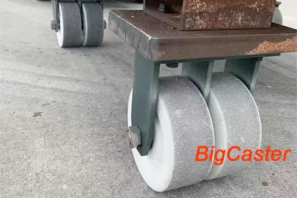
This extra heavy duty caster selection guide explains that process step by step. It is intended for industrial carts, machinery, fixtures, mobile platforms, material-handling equipment, container-handling systems and other equipment that must carry very high loads. If you already know your specifications, you can also review BigCaster’s extra heavy duty casters or send the application details listed near the end of this guide for a project-specific recommendation.
Important: A published load rating is only one part of a safe design. Final selection should be validated against the actual equipment, route, duty cycle and applicable safety requirements. Equipment used on slopes, at speed, around personnel or in other high-consequence conditions requires appropriate engineering review and testing.
Extra Heavy Duty Caster Selection Checklist
Before comparing models, collect the following information. Missing any one of these items can change the correct recommendation.
| Selection factor | Questions to answer | Why it matters |
|---|---|---|
| Total operating load | What is the maximum weight of the equipment, payload, accessories and temporary loads? | Establishes the minimum capacity required from the caster system. |
| Effective load-bearing casters | Can an uneven floor or flexible frame lift one caster clear of the floor? | The load may not be shared equally by every installed caster. |
| Movement method | Is the equipment pushed manually, power-assisted, towed or mostly stationary? | Changes rolling resistance, bearing, wheel and swivel requirements. |
| Speed and duty cycle | How fast, how far and how often will it move? | Continuous travel and towing generate heat and dynamic forces that static ratings do not describe. |
| Floor and route | Is the floor smooth, rough, cracked, soft, sloped or obstructed by joints and thresholds? | Influences wheel diameter, material, width, impact resistance and required push force. |
| Maneuvering space | Must the equipment pivot in place, track through long aisles or pass through narrow areas? | Determines the swivel/rigid layout, swivel radius and directional controls. |
| Environment | Are heat, cold, water, oil, chemicals, metal chips, washdown or outdoor exposure present? | Affects tread, core, bearing, grease, seal and finish selection. |
| Installation envelope | What mounting plate, bolt pattern, overall height and ground clearance are available? | Prevents interference and ensures the caster can be attached safely. |
| Control requirements | Does the equipment need wheel brakes, total locks, swivel locks, directional locks or floor locks? | Determines how it will stop, park and track. |
| Validation method | Will drawings, samples and loaded route tests be approved before production? | Confirms that the selected specification works in the real application. |
Step 1: Confirm That Extra Heavy Duty Is the Correct Caster Class
There is no universal industry boundary at which a heavy duty caster automatically becomes an extra heavy duty caster. Manufacturers use these terms for product families with different capacities, wheel constructions, plate sizes and intended service conditions.
Start with the application rather than the label. Extra heavy duty construction is usually worth considering when one or more of the following applies:
- The total equipment load creates a very high required rating per caster.
- Shock, floor joints or uneven load distribution create substantial dynamic demand.
- The equipment is moved frequently under a heavy load.
- Towing, powered movement or difficult floors impose forces beyond ordinary cart service.
- A larger mounting plate, reinforced fork, heavy swivel section or dual-wheel arrangement is required.
- Premature wheel, bearing or swivel wear has occurred with lighter caster designs.
Do not overspecify solely because a higher capacity sounds safer. An unnecessarily large caster may raise the equipment, increase the swivel envelope, add cost or make manual maneuvering harder. Compare the operating demands with the construction of both product classes. Our guide to heavy duty casters vs extra heavy duty casters explains the distinction in more detail.
Step 2: Create an Industrial Equipment Application Profile
A reliable industrial caster selection begins with a written application profile. This prevents a purchasing team from specifying only “four high-capacity swivel casters” while leaving the important engineering questions unanswered.
Define the equipment and load
Record:
- Empty equipment weight
- Maximum payload
- Weight of tooling, batteries, attachments, cables and accessories
- Location of the center of gravity
- Whether the load is centered, offset, shifting or suspended
- Whether operators may add loads that are not included in the normal payload
- Number and location of caster mounting points
- Frame stiffness and the possibility of chassis deflection
Use the maximum credible operating weight, not an average load. A tall or offset center of gravity may also affect equipment stability even when every caster has enough vertical capacity.
Describe every movement mode
State whether the equipment will be:
- Pushed or pulled by an operator
- Moved with a tugger, tractor or powered handle
- Repositioned occasionally for maintenance
- Rotated in place
- Driven through long straight aisles
- Loaded while stationary and then moved
- Subjected to side loading, docking impacts or abrupt direction changes
If the same machine is moved manually inside a work cell but towed between buildings, the caster must be evaluated for both conditions.
Map the complete travel route
Inspect the actual route instead of describing the floor as merely “concrete.” Note expansion joints, thresholds, gaps, gratings, ramps, drains, cracked areas, debris and changes in floor material. Measure the largest obstacles the wheel must cross. Also record aisle width, turning space, door clearances and any slope.
Document the environment
List the expected minimum and maximum temperatures, water exposure, cleaning process, chemicals, oils, cutting fluids, metal chips and outdoor conditions. Ask whether the equipment operates continuously in that environment or only passes through it.
Establish dimensional limits
Measure the mounting surface, available bolt pattern, maximum overall caster height, required ground clearance and space available for the wheel to swivel. Include nearby guards, leveling feet, tow bars, cables and frame members that could interfere with the caster.
The result is a practical set of caster requirements for industrial equipment—not just a load number.
Step 3: Confirm the Required Load Rating per Caster
For an initial screening calculation:
Required capacity per caster = maximum operating load × application allowance ÷ effective load-bearing casters
The application allowance must reflect the actual risk factors; it is not one fixed percentage for every project. Uneven floors, impact, towing, high frequency, concentrated loads and frame deflection can all increase demand.
Do not automatically divide a four-caster load by four. On an uneven floor, a rigid frame may temporarily place most of the load on three casters. A six-caster frame may not distribute weight equally unless the frame or suspension is designed to equalize it. The center of gravity can also overload one end or side of the equipment.
For example, consider equipment with a maximum operating weight of 8,000 kg. If the design review assumes that three of four casters may carry the effective load, the base load is approximately 2,667 kg per caster before any application allowance is applied. The final rated capacity must then be checked under the manufacturer’s stated rating conditions and against the selected speed, floor and duty cycle.
Capacity should refer to the complete caster assembly—not only the wheel. The wheel, wheel bearings, axle, fork, swivel section, mounting plate, fasteners and equipment frame all participate in the load path. The lowest suitable component or interface can limit the system.
Use the extra heavy duty caster load capacity guide for the full calculation method, or perform an initial estimate with the caster wheel load capacity calculator. BigCaster load-category pages identify the rating of an individual caster or wheel assembly; they are not the total capacity of a four-caster set.
Step 4: Define How the Equipment Will Move
The same vertical load can require very different extra heavy duty caster specifications depending on how it moves.
Manual push or pull
For manually moved equipment, starting force, continuous rolling force and swivel force are central selection criteria. Capacity alone does not tell an operator how difficult a loaded cart will be to move.
Generally, larger-diameter wheels pass over floor irregularities more easily. Harder tread materials often reduce rolling resistance on smooth floors, while resilient materials can reduce noise and protect floors. Bearing type, wheel alignment, caster layout and swivel geometry also influence push effort.
A high-capacity wheel that protects the floor but deforms substantially under load may be harder to start. Conversely, a very hard wheel may roll efficiently but transmit shock, create noise or damage a sensitive floor. The correct choice balances ergonomics with floor, load and durability requirements.
For equipment beyond reasonable manual force, do not treat a different caster as the only solution. A powered mover, revised route or other material-handling control may be required.
Powered towing
Powered towing introduces speed, distance, heat, repeated impact and lateral forces that may not be covered by a low-speed manual rating. Provide the maximum speed, normal speed, tow distance, trip frequency, turning radius and route condition.
Ask the supplier to confirm:
- Dynamic capacity at the proposed speed
- Suitable wheel and swivel bearings
- Heat buildup in tread and bearings
- Tread-to-core bond suitability
- Caster alignment and resistance to shimmy
- Swivel lead and turning behavior
- Need for rigid, swivel or directionally locked positions
- Inspection and maintenance intervals
Never assume a caster is towable simply because its static or low-speed rating exceeds the calculated load.
Occasional repositioning
Some machines remain stationary for months and move only during installation or maintenance. These applications may involve very low travel mileage but long periods of concentrated load. Check for tread compression set, flat spotting, floor marking and the way the equipment is stabilized during operation.
If leveling feet, jacks or machine mounts carry the operating load after positioning, define the safe procedure for transferring weight between the casters and supports.
Step 5: Choose the Wheel Material
When buyers ask for the “best casters for extremely heavy equipment,” the honest answer depends on the floor, environment and movement method. No wheel material is best in every condition.
| Wheel material | General advantages | Important trade-offs | Typical selection direction |
| Polyurethane on iron or steel core | High load capability with better floor protection and lower noise than bare metal; multiple formulations are possible | Tread hardness, thickness, bond, heat buildup and chemical compatibility must be matched to the duty | Heavy equipment on relatively smooth industrial floors where load, floor protection and rolling performance must be balanced |
| PA nylon | Hard, non-marking and relatively low rolling resistance on smooth floors; resistant to many common substances | Less cushioning; can transmit noise and impact; floor joints and concentrated contact stress require review | Heavy carts or equipment on smooth floors where easy rolling and cleanliness are important |
| MC nylon | High-strength cast nylon option for demanding loads; hard tread supports efficient rolling | Limited shock absorption and floor protection compared with resilient treads | Very heavy equipment on smooth, clean industrial routes |
| Cast iron | High capacity, low deformation and good resistance to metal chips in suitable environments | Noisy, transmits shock and can damage or mark floors; corrosion and debris must be considered | Slow-moving equipment on hard, durable floors where floor protection is secondary |
| All-steel | Very high load capability and resistance to severe mechanical conditions | Very hard on floors, noisy and offers almost no cushioning; corrosion and impact transmission require review | Specialized high-load, low-speed applications with suitable floors |
| Rubber | Quiet, shock-absorbing and floor-friendly | Usually higher rolling resistance and lower practical load capability than hard polyurethane, nylon or metal options of comparable size | Applications prioritizing cushioning and noise control, provided the required capacity is available |
Polyurethane wheels
Polyurethane casters are common in industrial equipment because the material can provide a useful compromise between load capacity, noise, floor protection and rolling performance. However, “polyurethane” is not a complete specification. The compound hardness, tread thickness, wheel diameter, core, bond system, temperature and duty cycle all matter.
Ask whether the published rating applies to the proposed speed and continuous run time. Under demanding travel, cyclic deformation can generate heat in the tread. Chemical exposure or excessive heat can also affect the tread or its bond to the core.
Nylon wheels
Nylon casters can be a strong choice for smooth floors when low deformation and efficient rolling are priorities. PA nylon and MC nylon are not interchangeable labels, so specify the actual material and verify its capacity, moisture behavior, chemical compatibility and temperature range.
Because nylon is hard, it transfers more vibration and impact into the caster and equipment than a resilient tread. Route quality becomes especially important at very high loads.
Cast iron and all-steel wheels
Steel caster wheels and cast iron wheels may suit specialized extra-heavy applications where floor damage, noise and vibration are acceptable. They resist compression and can tolerate conditions that would damage some soft treads, but the hard contact surface creates high local floor stress.
Confirm that the floor is suitable. Also evaluate corrosion protection, wheel hardness relative to the floor, shock transmission to sensitive equipment and the effect of debris under the wheel.
Rubber wheels
Rubber casters provide cushioning, quiet travel and good floor protection, but they generally require more force to roll than harder alternatives. For very heavy industrial equipment, verify that a suitable construction and capacity are available rather than selecting rubber solely for its tread characteristics.
Step 6: Select Wheel Diameter, Width and Overall Height
Wheel dimensions influence far more than load capacity.
Wheel diameter
A larger wheel generally rolls over joints, small debris and floor irregularities more easily than a smaller wheel. It can reduce the force required to keep equipment moving, particularly on imperfect floors. This is why “what size casters do I need for heavy equipment?” cannot be answered from load alone.
Choose diameter by balancing:
- Required load capacity
- Maximum obstacle or floor gap
- Manual push-force target
- Available overall height
- Required ground clearance
- Swivel radius and equipment footprint
- Speed and bearing limits
A larger diameter does not automatically make a caster stronger. Wheel material, width, hub design, bearings, axle, fork and swivel construction still determine the complete rating.
Wheel width and contact area
Wider wheels can provide more material and contact area, but they can also increase scrub and swivel effort when equipment pivots under load. Contact pressure depends on tread shape and deformation as well as nominal width. Soft floors, coatings and gratings may require a specific footprint.
Do not increase width without checking maneuverability. A wheel that carries the load comfortably in a straight line may still be difficult to swivel while stationary.
Overall caster height
Overall height is the distance from the floor to the mounting surface. It changes equipment height, working ergonomics, ground clearance and stability. Confirm it on the final caster drawing rather than estimating it from wheel diameter.
Swivel radius, offset and clearance
A swivel caster requires space for the wheel and fork to rotate around the swivel axis. Check the full swivel envelope against the frame, guards, tow bars and adjacent casters. Caster offset—also called swivel lead—affects maneuvering force and dynamic behavior, but a larger offset is not universally better. It can increase the space required to swivel and alter reaction forces in the mounting structure.
Step 7: Choose Single-Wheel or Dual-Wheel Casters
Dual-wheel casters place two wheels in one caster assembly. They are often considered when a project needs high capacity within a limited wheel diameter or overall height. The two contact patches may also help distribute floor load, depending on wheel material and construction.
Potential advantages include:
- Higher capacity within a constrained installation envelope
- A wider effective footprint
- Differential wheel action that can help the pair turn as the wheels rotate at different speeds
- Additional configuration options for specialized industrial equipment
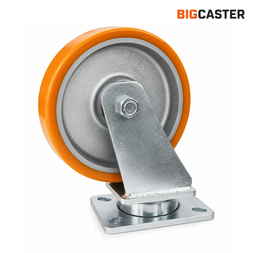
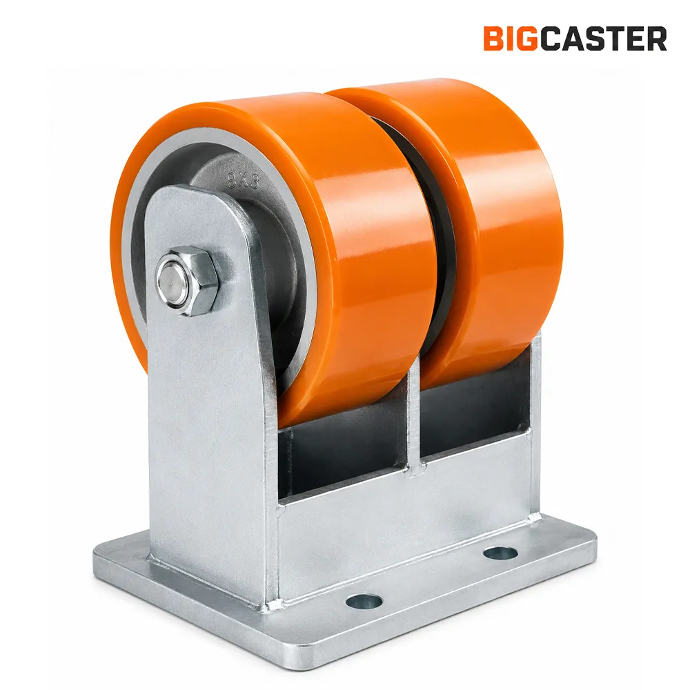
Potential trade-offs include:
- More components, bearings and possible debris-trap points
- Greater assembly width and clearance requirements
- Wheel scrub if the design or floor condition prevents effective differential action
- More complex maintenance and inspection
Do not assume that two wheels automatically double the rating of a comparable single-wheel caster. The fork, axle, bearings, swivel section and mounting plate still limit the complete assembly. Select single or dual wheels from tested assembly data and the available installation space.
Step 8: Select the Caster Layout
The caster configuration affects tracking, turning radius, stability and operator control as much as the individual wheel does.
| Caster layout | Main behavior | Suitable direction | Key caution |
| Two swivel + two rigid | Predictable straight tracking with steering from the swivel end | Conventional carts and equipment that travel through aisles | Requires room for a larger turn; orientation and push-handle end should be defined |
| Four swivel | High maneuverability and sideways movement | Tight work cells and equipment that must move in any direction | Can wander during long straight travel and may be difficult to control on slopes |
| Four swivel with directional locks | Omnidirectional movement when unlocked; selected casters can track like rigid units when locked | Equipment needing both tight maneuvering and straight travel | Lock engagement, wheel orientation and operating procedure must be clear |
| Multiple casters | Can support long frames or distribute high loads | Large platforms and long machinery bases | Load sharing is often unequal unless the frame or suspension is designed to equalize it |
Two swivel and two rigid casters
This is a practical starting point for many industrial carts. The rigid casters help the equipment hold a straight path, while the swivel casters steer. It is usually easier to control over a long distance than four free-swiveling casters.
The exact placement depends on the intended steering end and whether the equipment is pushed, pulled or towed. Very long equipment may need a different geometry to avoid excessive tire scrub during turns.
Four swivel casters
Four swivel casters allow lateral positioning and a small turning envelope, but each caster must rotate into the new direction. Under a very high stationary load, that swivel action can require significant force. Long-distance tracking can also be less stable.
Directional locks can give selected swivel casters a rigid-like orientation for straight travel, then release them for sideways positioning.
Multi-caster arrangements
Adding casters does not guarantee proportional capacity. A rigid frame on an uneven floor may bridge over intermediate casters. If all wheels must share the load, consider an equalizing or articulated arrangement and verify both vertical movement and stability. The frame itself must also distribute forces into the mounting points.
Step 9: Select the Swivel Section and Bearings
An extra heavy duty caster contains two distinct motion systems: the wheel rotates around its axle, and a swivel caster rotates around its vertical swivel axis. Their bearings solve different problems.
Wheel bearings
Wheel bearing selection affects capacity, rolling resistance, speed, maintenance and environmental protection. Common directions include:
- Plain bores or bushings for low-speed, simple applications
- Roller bearings for robust industrial movement
- Ball bearings for low rolling resistance and applications requiring appropriate speed capability
- Tapered roller bearings for high radial and thrust loads in suitable wheel designs
- Sealed or shielded arrangements where contamination control is important
The bearing name alone is not enough. Verify bearing size, seals, lubricant, axle fit, spacer arrangement, preload or end play, and its capacity within the complete wheel assembly.
Swivel bearings
The swivel section must carry vertical load while resisting side forces, impact and turning moments. Raceway size, ball arrangement, heat treatment, sealing and fork construction influence performance.
Kingpin vs kingpinless designs
A traditional kingpin caster uses a central fastener or rivet as part of the swivel assembly. A kingpinless caster typically uses an integrated raceway without a conventional central kingpin. Kingpinless designs are often selected for demanding shock and towing applications because they can distribute forces through a broad raceway and remove a common central component.
That does not mean kingpinless is always superior. A well-designed kingpin caster may be entirely appropriate for low-speed industrial equipment, and serviceability or adjustment can be valuable. Compare tested capacity, impact resistance, swivel effort, maintenance, mounting envelope and the actual duty cycle—not the label alone.
Step 10: Match the Caster to the Mounting Interface
The caster-to-frame connection is part of the safety-critical load path. A high-capacity caster attached to a thin, flexible or poorly reinforced frame will not deliver a reliable system.
For a top-plate caster, specify:
- Plate length and width
- Plate thickness
- Bolt-hole pattern and hole diameter
- Fastener size, grade, washers and locking method
- Required tightening torque or installation procedure
- Frame material and reinforcement
- Weld locations near the mounting area
- Access for installation and inspection
Do not select a mounting plate solely because its holes approximately align with an existing pattern. Edge distance, bearing area, bolt shear, pull-through, frame bending and fatigue require review.
If replacing an existing caster, record the complete installed geometry: plate size, bolt pattern, overall height, wheel diameter and width, swivel radius, brake clearance and orientation. Small dimensional differences can make the replacement unusable or change the way the equipment shares load.
For custom industrial equipment caster wheels, exchanging 2D drawings or 3D models before production reduces interpretation errors.
Step 11: Choose Brakes and Directional Controls
“Caster with brake” is incomplete. Different devices control different movements.
| Control type | What it controls | Common purpose | Limitation to verify |
| Wheel brake | Wheel rotation | Parking on a level surface | Does not prevent a swivel caster from changing direction |
| Swivel lock | Swivel rotation | Holds a swivel caster in a selected orientation | Does not stop the wheel from rolling |
| Total lock | Wheel and swivel rotation | Provides combined control at the caster | Actuation force, holding performance and access vary by design |
| Directional lock | Swivel orientation, commonly in one or more indexed positions | Converts swivel behavior to rigid-like tracking | Not necessarily a parking brake |
| Floor lock | Presses a pad against the floor and may unload part of the caster system | Stabilizes stationary carts in suitable conditions | Floor condition, adjustment and residual caster load must be checked |
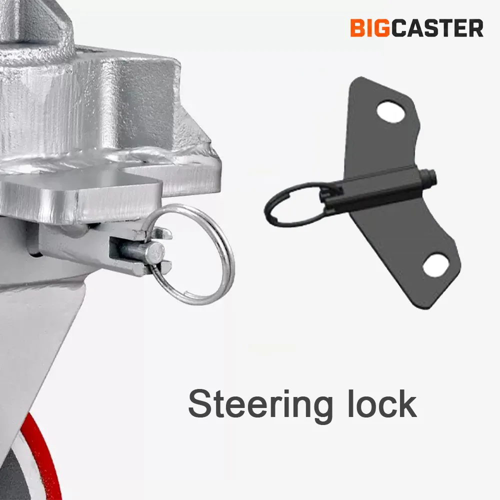
Choose controls by writing the required function first: stop rolling, prevent swiveling, improve straight tracking or stabilize the equipment. Then confirm access and ergonomics. Operators should not need to reach beneath a dangerous load or stand in a pinch zone to operate a lock.
Brakes are not automatically rated to hold equipment on a slope. A wheel brake may lose effectiveness because of tread compression, wear, contamination or changing load direction. If the equipment will encounter ramps or inclined floors, use a risk-assessed restraint and operating procedure specifically designed for the slope.
Step 12: Check the Operating Environment
Environmental compatibility applies to the entire caster, not just the tread.
| Condition | Items to specify or verify |
| High temperature | Continuous and peak temperature, exposure duration, radiant heat, wheel material, bearing, lubricant, seals and finish |
| Low temperature | Minimum temperature, material brittleness, lubricant viscosity, moisture and thermal cycling |
| Water or washdown | Wheel material, corrosion-resistant components, bearing protection, drainage, cleaning pressure and detergent |
| Oil or chemicals | Exact substance, concentration, exposure time, temperature and contact method; verify tread, core, bond, seals and finish |
| Metal chips or sharp debris | Tread cut resistance, wheel jamming risk, guards, seals and housekeeping controls |
| Dust or fibers | Bearing and swivel sealing, winding around axles, inspection access and cleaning schedule |
| Outdoor or UV exposure | Corrosion protection, water entry, sunlight, temperature range and storage conditions |
| Hygienic area | Cleanability, crevices, material compatibility, corrosion resistance and applicable facility standards |
A generic statement such as “chemical resistant” is not sufficient. Compatibility can change with concentration, temperature and exposure time. Provide the exact chemical and cleaning process to the wheel or caster supplier.
Step 13: Validate the Selection Before Production
For high-capacity caster selection, validation should occur in stages.
1. Application review
Review the completed application profile with the equipment designer, caster supplier, safety team and operations personnel. Resolve assumptions about load, speed, floor, configuration and environment.
2. Drawing review
Approve a drawing that identifies the material, wheel dimensions, overall height, plate and bolt pattern, swivel envelope, control locations and other critical features. Confirm left/right or leading/trailing orientation where applicable.
3. Sample inspection
Inspect representative samples for dimensions, wheel rotation, swivel action, brake or lock function, mounting fit and interference. A free-spinning unloaded sample is not a substitute for a loaded evaluation.
4. Loaded route test
Test at the maximum intended operating load on the real route. Evaluate:
- Starting and sustained push or pull force
- Steering and swivel effort
- Straight-line tracking
- Threshold and joint crossing
- Noise and vibration
- Floor marking or damage
- Brake and lock operation
- Component temperature after the intended duty cycle
- Stability during turns, stops and load transfer
- Clearance throughout the swivel range
For powered movement, test at controlled speeds up to the approved operating limit and inspect for shimmy, tread heating, bond distress, looseness and abnormal wear.
5. Production approval and maintenance plan
After testing, freeze the approved specification and define incoming inspection criteria. Establish intervals for checking tread wear, wheel damage, axle condition, bearing play, swivel looseness, mounting fasteners, welds, brakes, locks and lubrication.
Extra Heavy Duty Caster Specification Worksheet
Use this worksheet when requesting a quotation or documenting the approved design.
| Specification field | Project requirement |
| Equipment name and function | |
| Empty equipment weight | |
| Maximum payload | |
| Maximum total operating load | |
| Center-of-gravity location | |
| Number of caster positions | |
| Effective load-bearing casters used in calculation | |
| Required capacity per caster | |
| Desired caster class or product series | |
| Manual, powered or towed movement | |
| Normal and maximum speed | |
| Travel distance per cycle | |
| Cycles or operating hours per day | |
| Floor material and condition | |
| Largest joints, gaps or thresholds | |
| Slope or ramp details | |
| Indoor or outdoor use | |
| Minimum and maximum temperature | |
| Water, washdown, oil or chemical exposure | |
| Debris, chips, dust or fibers | |
| Preferred wheel material | |
| Wheel diameter and width limits | |
| Maximum overall height | |
| Required ground clearance | |
| Single-wheel or dual-wheel preference | |
| Swivel and rigid caster quantities | |
| Wheel bearing requirement | |
| Swivel construction requirement | |
| Mounting plate dimensions | |
| Bolt pattern and hole diameter | |
| Brake, total lock or directional lock | |
| Noise, floor protection or non-marking requirement | |
| Applicable standards or internal specifications | |
| Drawing, sample and test approval requirements | |
| Target quantity and delivery schedule |
Selection Examples for Common Industrial Conditions
These examples show how operating conditions change the selection direction. They are not final product recommendations.
| Application condition | Initial selection direction | Questions that still need answers |
| Manually pushed machinery on smooth coated concrete | Larger-diameter polyurethane or nylon wheel; prioritize low rolling and swivel force; consider two swivel + two rigid | Maximum operator force, floor-protection requirement, turning space, load distribution |
| Towable heavy platform crossing expansion joints | Large-diameter wheel, dynamic/towing-rated assembly, suitable bearings and controlled swivel configuration | Speed, trip length, joint dimensions, heat buildup, shimmy control |
| Stationary machine repositioned for maintenance | Evaluate long-term tread deformation, total locks or separate leveling supports | Time under load, movement frequency, floor marking, load-transfer procedure |
| High-load cart in a tight work cell | Four swivel casters or swivel casters with directional locks; check swivel effort under load | Required pivoting, aisle width, straight-travel distance, lock access |
| Equipment exposed to metal chips | Hard, cut-resistant wheel direction with protected bearings and cleaning plan | Floor suitability, chip size, wheel-jam risk, noise and shock tolerance |
| Washdown or corrosive area | Corrosion-resistant construction, compatible wheel and protected bearings | Chemical, concentration, temperature, pressure, hygiene requirements |
| Low-profile heavy equipment | Dual-wheel or compact high-capacity arrangement may help | Maximum overall height, assembly width, floor loading, turning effort |
12 Common Extra Heavy Duty Caster Selection Mistakes
- Dividing the load equally by every installed caster. Uneven floors and frame deflection can reduce the number of casters carrying the load.
- Using empty equipment weight. Payload, tooling, batteries and attachments belong in the maximum operating load.
- Selecting by capacity alone. A technically strong caster may still roll poorly, damage the floor or fail to fit.
- Applying one arbitrary safety factor to every application. The allowance should reflect specific dynamic, environmental and load-distribution risks.
- Ignoring speed and distance. Towing and continuous travel can create heat and forces not represented by a low-speed rating.
- Choosing the smallest wheel that carries the load. Small wheels may struggle at joints, thresholds and debris even when their nominal capacity is sufficient.
- Assuming harder is always better. Hard wheels may lower deformation but increase noise, shock and floor stress.
- Assuming dual wheels double capacity. The complete caster assembly and mounting interface set the rating.
- Using four swivel casters without considering tracking. Maximum maneuverability can reduce control during long straight travel.
- Treating every brake as the same device. Wheel brakes, total locks, directional locks and floor locks perform different functions.
- Ignoring the mounting structure. Thin plates, weak welds, incorrect fasteners and poor reinforcement can undermine a high-capacity caster.
- Skipping a loaded route test. Real floors, real clearances and real operating cycles reveal issues that a catalog comparison cannot.
Information to Send BigCaster for a Recommendation
To receive a useful recommendation for casters for heavy industrial equipment, send more than a target capacity. Include:
- Equipment description, drawing and photographs
- Empty weight, maximum payload and total operating load
- Number and position of casters
- Center-of-gravity or uneven-load information
- Movement method: manual, powered or towed
- Maximum speed, distance, frequency and turning requirements
- Floor type, route photos and obstacle dimensions
- Temperature, water, chemicals and debris exposure
- Maximum overall height and available swivel space
- Mounting plate and bolt-pattern dimensions
- Required wheel material or performance priorities
- Brake, total-lock or directional-control needs
- Quantity, project schedule and validation requirements
If some values are unknown, identify them as unknown rather than estimating silently. The application can then be reviewed around those open items.
How BigCaster Supports Industrial Equipment Projects
BigCaster manufactures heavy duty and extra heavy duty caster solutions for industrial carts, equipment, logistics systems, container handling and other high-load applications. Available wheel-material directions include polyurethane, rubber, PA nylon, MC nylon, cast iron and all-steel constructions.
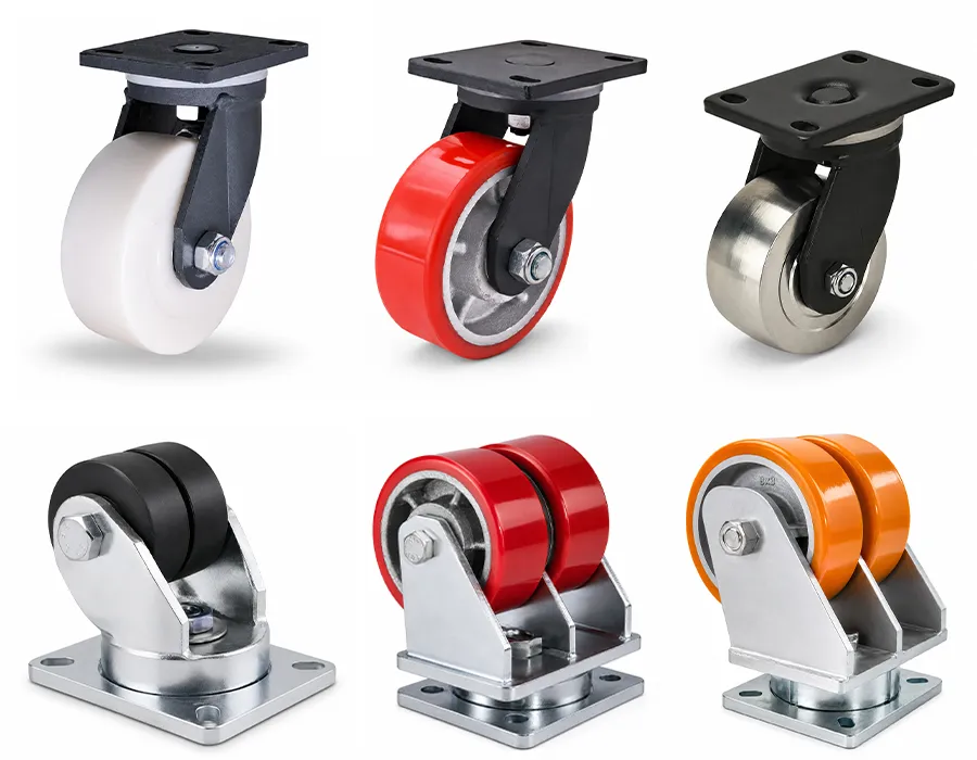
Projects can be reviewed by required capacity, movement method, floor, dimensions, mounting and environment. Custom load-capacity and configuration requirements can also be discussed. BigCaster operates under an ISO 9001 quality management system and can support projects without a fixed minimum order quantity, subject to the practical requirements of the selected or custom construction.
Browse the extra heavy duty caster range after completing the worksheet, then compare the candidate models against the full application—not only the load label.
Frequently Asked Questions
What information is needed to choose extra heavy duty casters?
At minimum, provide maximum total load, number of caster positions, expected load distribution, movement method, speed, duty cycle, floor condition, route obstacles, environment, available dimensions, mounting pattern and control requirements. A drawing and route photos make the review more reliable.
How much load capacity should each caster have?
Divide the maximum operating load—plus an application-appropriate allowance—by the number of casters expected to carry the load effectively. Do not automatically use the total number installed. Uneven floors, frame stiffness and an offset center of gravity may reduce effective load sharing. See the load capacity guide for the complete method.
Are larger caster wheels always better for heavy equipment?
No. A larger diameter generally improves obstacle crossing and can reduce rolling effort, but it also increases overall height and may require more swivel clearance. Capacity depends on the entire wheel and caster construction, not diameter alone.
What is the best caster wheel material for extremely heavy equipment?
There is no universal best material. Polyurethane can balance load, floor protection and noise; nylon can provide hard, efficient rolling on smooth floors; steel or cast iron can serve specialized high-load conditions; rubber prioritizes cushioning and quiet movement where a suitable capacity is available. Match the material to the floor, speed, temperature, chemicals and duty cycle.
Should heavy equipment use swivel or rigid casters?
Use a layout that matches the travel path. Two swivel plus two rigid casters often provide predictable tracking. Four swivel casters allow sideways positioning but may be harder to control over long distances. Directional locks can combine both behaviors in one system.
When should I choose dual-wheel casters?
Consider dual wheels when high capacity must fit within a limited diameter or overall height, or when the application benefits from a wider footprint. Confirm complete assembly capacity, width, swivel clearance, floor contact and maintenance needs. Do not assume capacity automatically doubles.
Are kingpinless casters always better than kingpin casters?
No. Kingpinless construction is often useful for demanding shock, towing and high-load service, but a suitable kingpin design can perform well in many low-speed industrial applications. Compare tested performance, swivel effort, maintenance and operating conditions.
Can caster brakes safely hold equipment on a slope?
Do not assume they can. Many caster brakes are intended for parking on level surfaces and are not certified slope restraints. Inclined operation requires a specific risk assessment, verified holding device and safe procedure.
Can extra heavy duty casters be customized?
Yes. Capacity, wheel material, dimensions, mounting, bearings, finish and control features may be adapted when a standard product does not meet the application. Custom work should begin with complete operating data and finish with drawing approval and representative testing.
Final Selection Principle
The best way to choose extra heavy duty casters is to treat the caster as part of the equipment system. Calculate a realistic capacity per caster, then evaluate how the equipment moves, what the wheel contacts, how the frame carries the load and what the operating environment does to every component.
A complete decision should answer five questions:
- Can the caster and mounting structure carry the real load under the real duty cycle?
- Can the equipment start, roll, steer and stop as required?
- Will the wheel protect—or at least remain compatible with—the floor and environment?
- Does the caster fit the available height, mounting pattern and swivel envelope?
- Has the final configuration been verified by drawing review and a representative loaded test?
When all five answers are supported by application data, the result is more than a high load rating. It is an extra heavy duty caster specification that can be purchased, tested and maintained with confidence.